


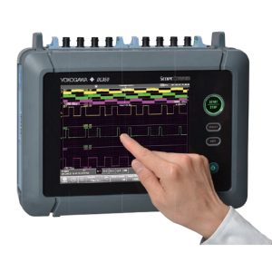
The Yokogawa DL850E ScopeCorder (Oscilloscope/Recorder) is designed for engineers working in the automotive and railway industry. A common measurement challenge is to combine measurements of electrical signals, physical performance parameters, indicated by sensors, together with CAN- or LIN-bus data transmitted by the powertrain management system. A Yokogawa DL850E ScopeCorder addresses this requirement by providing a thorough insight into the dynamic behavior of the electromechanical system. The result is a considerable saving of time compared to other approaches such as analysis on a PC or the use of other software.
The DL850E ScopeCorder can display CAN- and/or LIN-protocol communication data as trend waveforms on the display by using the CAN Bus Monitor Module (720240) or CAN & LIN Bus Monitor Module (720241). By identifying the correlation between communication data on the vehicle-installed LAN and analog data such as voltage, temperature, and sensor signals or the ECU’s control logic signal, a vehicle’s overall LAN system can be evaluated.
Yokogawa DL850E Features:
- Continuous data recording
- Real-Time Measurement of Electrical Power – /G3 option
- Real-Time Mathematical Computations and Digital Filtering – /G5 option
- User defined computations – /G2 option
- Choose from 17 different types of input modules
- Continuous data recording for durability test and/or surveillance test , Max. 128-CH measurements
- Record measurements up to 200 days to internal hard disk
- Memory offers long duration measurement and two instantaneous zoom locations —2 GPoint memory
- Powerful trigger functions with unique features such as Dual-Capture & History Memory
- New power MATH trend calculations such as Active Power, Power Factor, Integrated Power and Harmonics
- GPS or IRIG time synchronization
- Flexible and swappable input modules with built-in signal conditioning
- Capture high speed transients during long term recording using “Dual capture”
- “History Memory”, so you’ll never miss an abnormal waveform
- Time synchronization for accurate measurements
- Real time filter and High resolution mode — for precision waveform observation
- Processes noise rejection and executes powerful computations in real time
- Automated measurement of waveform parameters — Automatically display numeric values
- Computation functions — quickly analyze information ‘hiding’ in waveforms
- Multi-channel and continuous measurement (Power +)
• 6-input (3-voltage and 3-current) waveforms for 2-system simultaneous measurement

Yokogawa DL850E ScopeCorder Specifications: | |||
| Memory (main unit) | |||
| Max. Record length | Standard | 250 Mpts (1 CH) 10 Mpts/CH (16 CH) | |
| /M1 option | 1 Gpts (1CH) 50 Mpts/CH (16 CH) | ||
| /M2 option | 2 Gpts (1CH) 100 Mpts/CH (16 CH) | ||
| * Dependent on modules and no. of channels | |||
| Channels | 16CH/Slot, 128CH/Unit | ||
| (Maximum simultaneous display waveform is 64 waveforms x 4 screen selectable) | |||
| Number of plug-in module slots | 8 total Max 4 for 720210 modules | ||
| Time axis accuracy | ±0.005% | ||
| Display—- | |||
| Display: | 10.4-inch TFT color LCD monitor, 1024×768(XGA) | ||
| Display res. of waveform display: | selectable either 801×656 (normal waveform display) or 1001×656 (wide waveform display) | ||
| Display format: | Max 3 simultaneous displays available In addition to main, 2 more waveforms available among zoom 1, zoom 2, XY1, XY2, FFT1, FFT2 (/G2 option), Vector (/G5 option), Bar graph (/G5 option) | ||
| Functions | |||
| Acquisition mode: | Normal | Normal waveform acquisition | |
| Envelope | Maximum sample rate regardless of record time, holds peak value | ||
| Averaging | Average count 2 to 65536 (2n steps) | ||
| Box (av.) | Increase A/D resolution up to 4 bits (max 16 bits) | ||
| Dual capture | |||
| Main waveform (low speed) | Maximum sample rate | 100kS/s (roll mode region) | |
| Maximum record length | 1G point (/M2, 1CH) | ||
| Capture waveform (high speed) | Maximum sample rate | 100MS/s | |
| Maximum record length | 500k point | ||
| Performs data acquisition on the same waveform at 2 different sample rates | |||
| Real Time HD Recording | |||
| Maximum sample rate | Maximum1MS/s (1CH used), 100kS/s (16CH used) depends on channel used | ||
| (/HD0,/HD1 option) | Capacity | Depends on HDD vacant capacity | |
| Action | Data can be stored in the hard disc at the same time of acquisition in accordance with trigger mode | ||
| Roll mode: | It is effective when the trigger mode is set to auto/auto level/single/ON start, and time axis is greater than 100ms/div. | ||
| History memory: | Maximum 5000 pages | ||
| PC Card Interface | |||
| Slots | 2 (front panel (1), rear panel (1)) | ||
| Supported card | GPIB card (National Instruments NI PCMCIA-GPIB card), Flash ATA memory card (PC card TYPE II), CF card + adapter card, and various hard disk type PC cards | ||
| Storage | |||
| SD card slot: | Memory cards conforms to SD, SDHC | ||
| USB memory: | Mass storage device which conforms to USB Mass Storage Class Ver.1.1 | ||
| External HDD | Hard disc conforms to eSATA, FAT32 | ||
| Built-in HDD | 2.5 inch, 500GB, FAT32 | ||
| Environment | |||
| Power supply: | 100 to 120VAC/220 to 240VAC (automatic switching) — 50/60Hz | ||
| Power consumption: | Max 200 VA | ||
| Operating Temperature: | 5C° to 40C° | ||
| Dimensions: | Approx. 355 mm (W) x 259 mm (H) x 202mm (D), excluding the grip and projections | ||
| Weight: | Approx. 800 g | ||


Reviews
There are no reviews yet.