 Promotions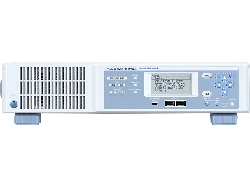
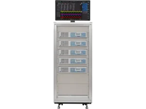
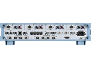
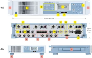


Your test rack is running out of room — and your DC bus is running out of headroom
Two things have happened to power electronics test benches over the last few years, and neither of them has been kind to the equipment already sitting in the rack.
The first is voltage. EV platforms have moved to 800 V architectures. Utility-scale PV strings and battery energy storage systems routinely sit at 1500 V DC and climb from there. Most precision power analysers on the market top out at 1000 V direct input, which means the moment your DC bus exceeds that, you’re bolting an external voltage divider onto the front of the instrument. That divider brings its own amplitude error, its own phase shift, its own temperature coefficient — and every one of those errors stacks on top of the analyser’s own uncertainty. You end up quoting an efficiency figure to three decimal places that your measurement chain can’t actually support.
The second is channel count. A dual-inverter e-Axle needs DC bus, two three-phase AC outputs, and mechanical power from two motors — measured simultaneously, on the same time base. A multi-string PCS needs a measurement point per string plus the grid side. Meanwhile the rack itself hasn’t grown. Every rack unit an instrument occupies is a rack unit unavailable to the power supply, the load bank, or the ScopeCorder.
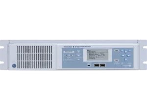
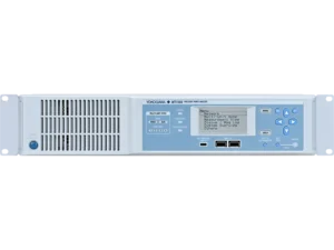
The Yokogawa WT1500 Precision Power Analyzer was designed around both problems at once.
What the WT1500 actually does differently
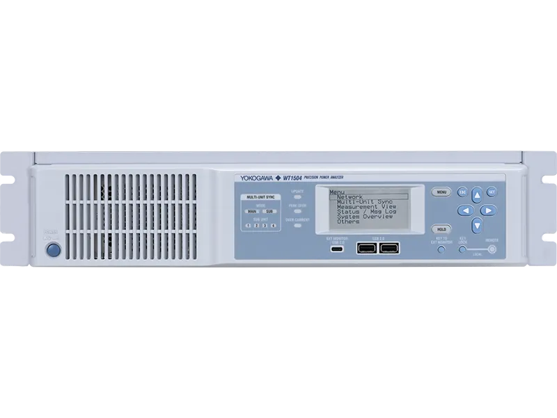
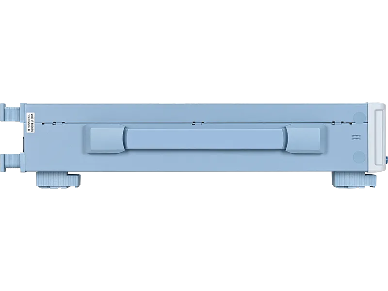
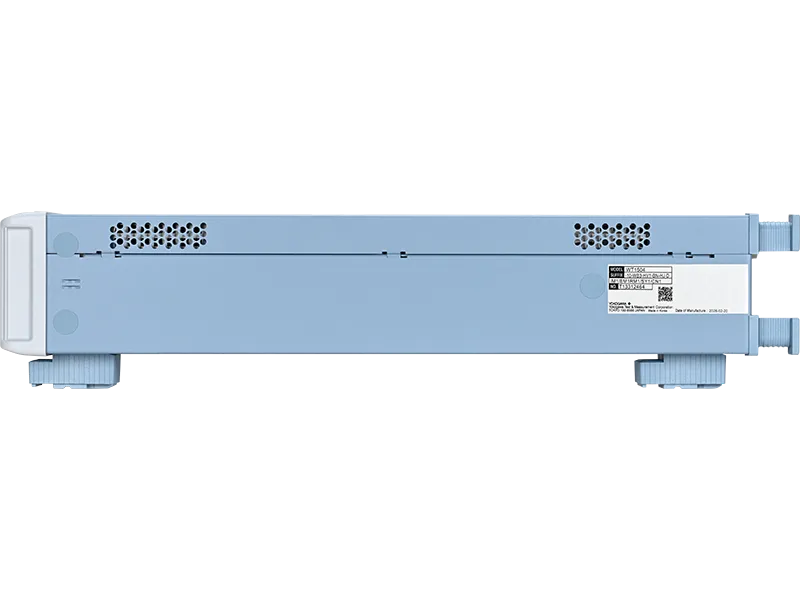
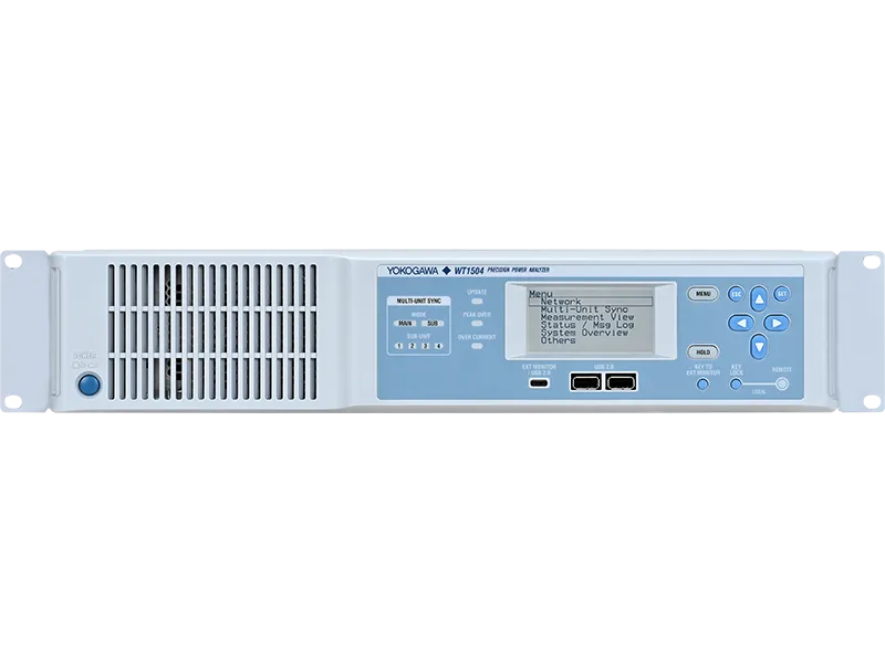
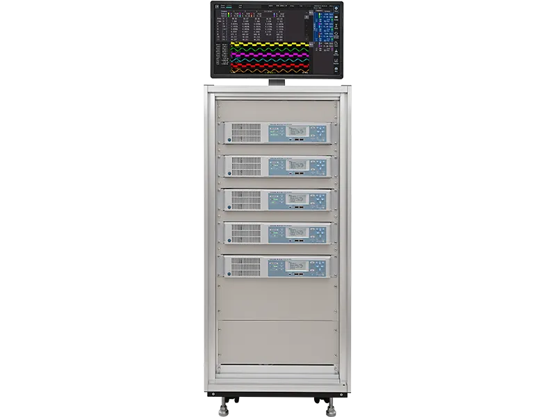
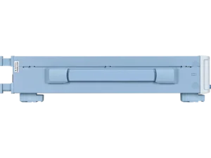
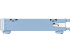
Released in August 2026, the WT1500 is the newest member of the WT series and the first to offer 2000 V direct input. It sits in a 2U (approximately 88 mm) JIS/EIA rack-mount chassis, and inside that chassis you can fit up to four power measurement elements and up to four motor evaluation channels.
The headline number is ±0.038% total power accuracy at DC and at 50/60 Hz. That figure is the sum of the two accuracy terms Yokogawa specifies: ±0.018% of reading plus ±0.02% of range. Read that way it tells you something useful — the range term dominates when your signal sits low in the range, so range selection still matters, but at or near full range you’re working with a genuinely reference-class instrument. For context, within Yokogawa’s own line-up the WT1500 is specified tighter at DC than both the WT5000 (±0.07%) and the WT1800R (±0.1%).
Low power factor performance is where efficiency measurements usually fall apart, and the WT1500 holds ±0.07% of apparent power at 50/60 Hz with a power factor of zero. That’s the specification that governs no-load inverter testing and standby loss measurement, where the active power component is a small fraction of the apparent power flowing.
Choose your elements: high voltage or wide bandwidth
The WT1500 doesn’t force a single compromise on you. Each input element is specified at order time as one of two types, and you can mix them freely within one chassis.
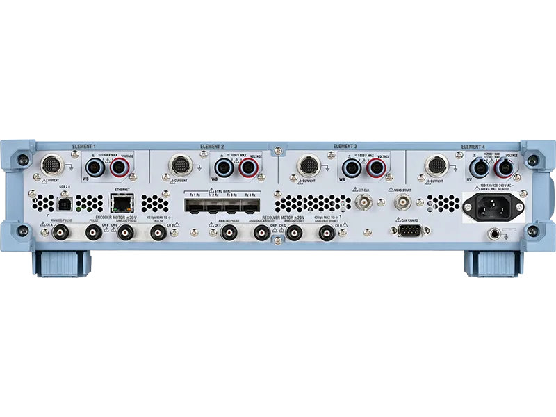
HV (High Voltage) elements take direct measurements up to 2000 V, with voltage ranges of 6 / 15 / 30 / 60 / 150 / 300 / 600 / 1000 / 2000 V at crest factor 3. Frequency band runs DC to 300 kHz typical. This is the element for battery packs, DC links, PV strings and ESS DC buses.
WB (Wide Bandwidth) elements cover ranges to 1000 V with a DC to 2 MHz typical frequency band. This is the element for SiC and GaN converter work, fast-switching inverter stages, and anywhere the harmonic content of the switching waveform genuinely matters to your loss budget.
A typical PCS evaluation configuration might be three WB elements and one HV element — three-phase AC on the wideband inputs, high-voltage DC on the HV input, in a single 2U box. That combination is ordered as a WT1504-10-WB3-HV1.
Both element types share the same acquisition front end: 16-bit resolution, 2.5 MS/s sample rate, with voltage and current converted simultaneously so there’s no inter-channel skew to correct for.
Built for the rack, not the bench
Where the WT1500 separates itself from general-purpose power analysers is in how it expects to be operated — which is to say, mostly not by hand.
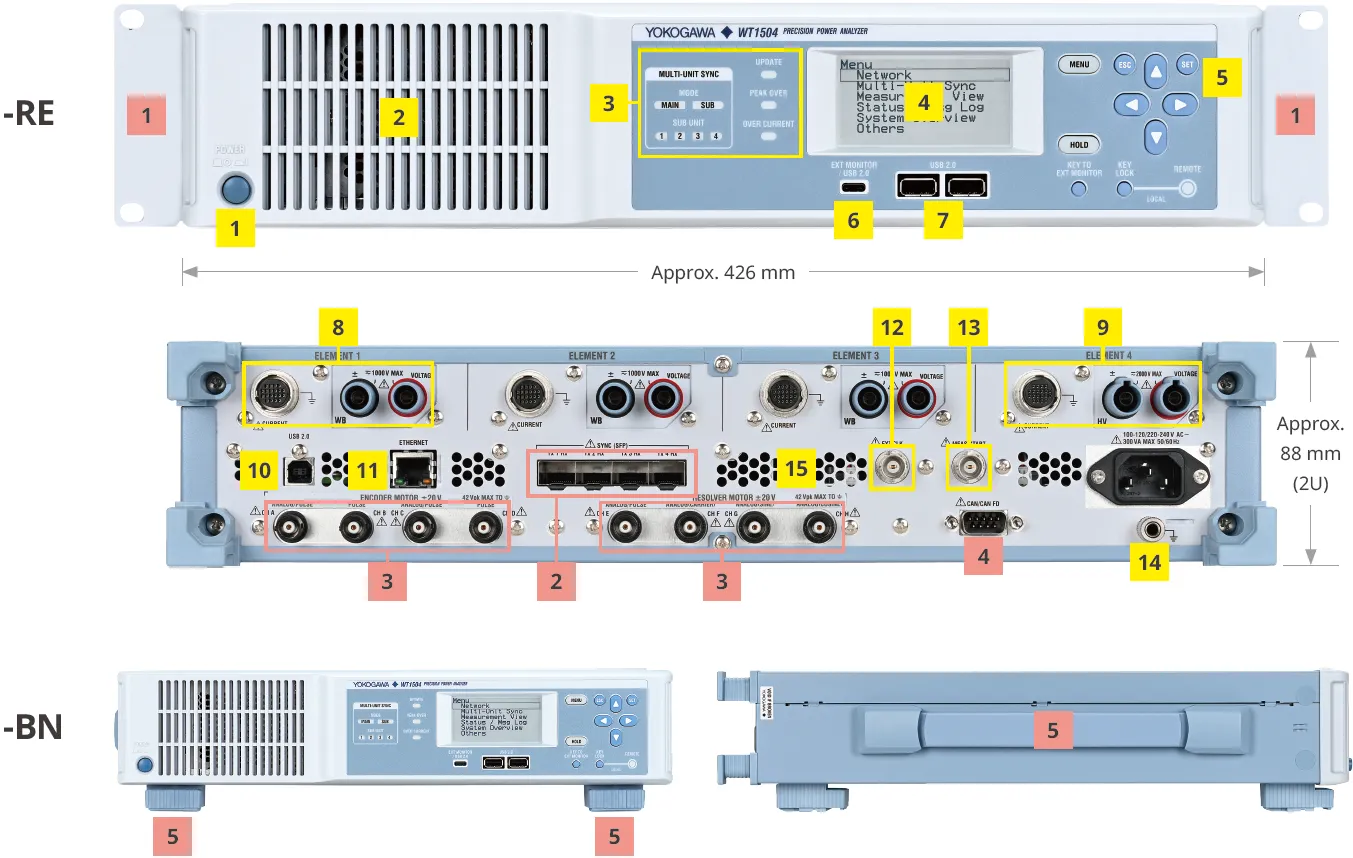
The front panel carries a small 2.9-inch monochrome LCD and a handful of control keys. That’s deliberate. Real operation happens through the built-in web server (browser-based control and monitoring over Ethernet), through the free WTViewerEfree PC software, or through direct communication commands over Ethernet or USB. If you do want a local display, a USB-C port drives an external monitor at 1280 × 720, and connecting a touchscreen gives you full touch control of the menus.
For data out, the instrument speaks the languages an automated test system actually uses:
- CAN / CAN FD (the /CN1 option) streams measurement data straight onto the vehicle bus at each update interval — up to 512 items depending on bit rate — for direct integration with ECU and control systems.
- Low-latency UDP provides continuous real-time measurement data for closed-loop control and fast anomaly detection.
- Modbus/TCP server suits long-duration monitoring on industrial pump and fan rigs.
- IEEE 1588 (PTP v2) time synchronisation timestamps WT1500 data against compatible instruments — including the SL2000 ScopeCorder — to roughly ±10 µs, so power values and captured waveforms line up on one timeline.
- Standard Ethernet services include VXI-11, Socket, HiSLIP, FTP and web server over 1000BASE-T.
Auto-setup functions handle production-line signal variation without an operator standing over the instrument: 10 ms data updates, automatic frequency tracking, adaptive filtering, and measurement down to 0.1 Hz.
Twenty channels when four isn’t enough
When one chassis runs out of inputs, the /SY1 multi-unit synchronisation option links up to four sub-units to a main unit over optical fibre (SFP transceivers, up to 300 m). That gives you 20 power channels and 20 motor channels in one synchronised system, with ±400 ns synchronisation accuracy between units.
Critically, it behaves as one instrument. The main unit configures ranges, filters, scaling and wiring on every sub-unit, collects all normal and harmonic measurement values plus compressed waveform data, and saves the whole system’s setup in a single file. Data from sub-units feeds directly into the main unit’s efficiency calculations and user-defined computations.
Please note: Yokogawa has stated the /SY1 option will be released later, and can be added to a purchased unit via an option upgrade licence. If multi-unit synchronisation is on your critical path, talk to us about current availability before you commit to a delivery date.
Motor evaluation — encoder and resolver, mixed freely
Five motor evaluation options are available, and you select one at order time:
| Option | Channels A–D | Channels E–H |
|---|---|---|
| /EM1 | Encoder input (up to 2 motors) | — |
| /RM1 | Resolver input (1 motor) | — |
| /EM2 | Encoder input (up to 2 motors) | Encoder input (up to 2 motors) |
| /RM2 | Resolver input (1 motor) | Resolver input (1 motor) |
| /EM1RM1 | Encoder input (up to 2 motors) | Resolver input (1 motor) |
The instrument computes rotating speed, torque, synchronous speed, slip and motor output alongside the electrical measurements. Resolver channels carry a 1 MHz typical bandwidth on the carrier, sine and cosine inputs, with electrical angle measurement error of ±0.1° typical and a maximum display of 150,000 rpm. Built-in Ld/Lq calculations support vector analysis of permanent magnet synchronous motors.
Because encoder and resolver channels can be mixed in one instrument, a test cell running two different motor types doesn’t need two different analysers.
Where it earns its keep
Power conditioning systems and energy storage. Multi-string PCS architectures above 1500 V need many measurement points at high accuracy. The 2000 V HV element removes the external divider from the chain, and multi-unit synchronisation scales the channel count to match the string count.
Data centre and EV fast-charger power supplies. AC/DC conversion efficiency measured input-to-output in a single unit, with the WT1500 holding specification across 1% to 130% of range — which matters when the load is dynamic rather than steady-state.
EV powertrain and e-Axle efficiency. Simultaneous DC, three-phase AC, torque and speed acquisition across multiple power paths, with results streamed onto CAN FD for the control system.
Industrial motor duration testing. Long-term watt-hour and ampere-hour integration on inverter-driven pumps and fans, monitored over Modbus/TCP.
Ordering the WT1500 — and the part people get wrong
The WT1500 is a configured instrument, not a shelf item, and the model code carries real consequences. You select the number of elements (WT1501-10 through WT1504-10), the HV/WB split within those elements, the installation type (-BN benchtop, -RE EIA rack, -RJ JIS rack), menu language, power cord, and then the additional options: /M1 32 GB memory, one motor evaluation option, /SY1, and /CN1.
The single most important thing to understand before you order: the WT1500 has no direct current input. All current measurement is made through a Yokogawa current sensor or clamp probe, and those are sold separately. The instrument provides sensor power and supports automatic sensor recognition with ratio and phase compensation for compatible models, but the sensor itself is a separate line on the order. Sensor options run from the CT60 (60 A peak, DC to 800 kHz) through the CT1000A and CT1000S split-core (1000 A) to the CT2000A (2000 A RMS), plus AC clamp probes. Getting this wrong is the difference between an instrument that works on day one and one that sits in its box.
For Australian sites, specify the -R (AS Standard) power cord. And if you’re measuring above 1000 V on an HV element, you’ll need the 758932 high-voltage safety terminal adapter set together with appropriately rated cable.
Why buy your WT1500 through us
We supply and support Yokogawa test and measurement equipment to Australian labs, OEMs and production facilities, and we’ll work through the model and suffix code with you before anything is ordered — element mix, motor option, rack format, sensor selection and cable set — so the instrument that arrives is the one your test plan actually needs.
Every instrument ships with the manufacturer’s calibration certificate, and we can arrange ongoing calibration through our service partners. Our team can talk through channel-count planning, sensor pairing, and integration questions with people who’ve configured these systems before.
Request a configuration and quote below, or send through your measurement points and we’ll come back with a recommended model code.
Technical Specifications
| Specification | Value | Why It Matters |
|---|---|---|
| Input elements | 1 to 4 (WT1501-10 / WT1502-10 / WT1503-10 / WT1504-10) | Buy the channel count your test plan needs; four channels covers DC bus plus three-phase AC in one chassis |
| Element types | HV (High Voltage) and WB (Wide Bandwidth), mixable in one unit | One instrument handles both the high-voltage DC link and the fast-switching AC stage |
| Max voltage range — HV element | 2000 V (ranges 6/15/30/60/150/300/600/1000/2000 V at CF3) | Series-first 2000 V direct input removes external dividers and their added uncertainty from 1500 V DC systems |
| Max voltage range — WB element | 1000 V (ranges 6/15/30/60/150/300/600/1000 V at CF3) | Covers three-phase mains and inverter output without the bandwidth penalty of an HV element |
| Frequency bandwidth | WB: DC to 2 MHz typical; HV: DC to 300 kHz typical | Wideband elements capture SiC/GaN switching content; HV elements prioritise voltage headroom |
| Power accuracy (DC) | ±(0.018% of reading + 0.02% of range) — ±0.038% total | Tighter at DC than the WT5000 (±0.07%) and WT1800R (±0.1%) in Yokogawa’s own comparison |
| Power accuracy (50/60 Hz, PF=1) | ±(0.018% of reading + 0.02% of range) — ±0.038% total | Reference-class mains-frequency efficiency measurement |
| Power accuracy (50/60 Hz, PF=0) | ±0.07% of apparent power (S) | Governs no-load inverter and standby-loss measurement, where active power is a small fraction of VA |
| Current input | Via current sensor only. Sensor-current ranges 25 mA–1 A; sensor-voltage ranges 50 mV–5 V (CF3) | No direct current input — a Yokogawa current sensor is required and sold separately |
| A/D converter | 16-bit, 2.5 MS/s, simultaneous voltage and current conversion | No inter-channel skew between V and I to correct for in power computation |
| Data update rate | Auto / 10 ms / 50 ms / 100 ms / 200 ms / 500 ms / 1 / 2 / 5 / 10 / 20 s | 10 ms updates keep pace with production-line cycle times; long intervals suit low-frequency work |
| Lower measurement frequency | 0.1 Hz (at 20 s update or Auto mode) | Covers very low-frequency drive and grid-tie behaviour |
| Harmonic measurement | PLL sync; fundamental 0.1 Hz–2.6 kHz; analysis to 260 kHz; up to 100th order | Full harmonic distortion, K-factor, THD and telephone influence factor analysis without a separate instrument |
| Wiring systems | 1P2W, 1P3W, 3P3W (incl. 3V3A / 3V3AR), 3P4W, with delta transformation | Handles single-phase and three-phase configurations simultaneously across elements |
| Motor evaluation | /EM1, /RM1, /EM2, /RM2, /EM1RM1 — up to 4 encoder motors or 2 resolver motors | Electrical and mechanical power measured on one time base; encoder and resolver mixable |
| Electrical angle error | ±0.1° typical (resolver); max display 150,000 rpm | Supports vector analysis and Ld/Lq calculation for PMSM development |
| Multi-unit synchronisation | /SY1 option — up to 4 sub-units, 20 power + 20 motor channels, ±400 ns | Scales past four channels without losing a common time base. Availability: see publisher note |
| Sync interconnect | SFP optical (720941 module), 50/125 µm multimode fibre, max 300 m | Optical link keeps synchronisation clean across a large test hall |
| CAN output | /CN1 option — CAN / CAN FD, D-sub 9-pin, up to 512 items per update | Streams live measurement data to ECU and control systems on the vehicle bus |
| Ethernet | 1000BASE-T / 100BASE-TX / 10BASE-T; VXI-11, Socket, HiSLIP, Modbus/TCP, FTP, UDP, web server | Remote control and data streaming without proprietary drivers |
| Time synchronisation | IEEE 1588-2008 (PTP v2), slave only; ~±10 µs correlation with SL2000 ScopeCorder | Aligns power readings with captured waveforms for event and timing verification |
| Internal memory | 2 GB standard, 32 GB with /M1 option | Binary storage up to 1 GB per file, auto-converted to CSV |
| Display | 2.9-inch monochrome STN LCD, 256 × 128; external monitor via USB-C at 1280 × 720 | Small front panel saves rack depth; touchscreen monitor gives full local control when needed |
| Power supply | 100–120 VAC / 220–240 VAC, 48–63 Hz, max 300 VA | Direct connection to Australian mains with the -R (AS Standard) power cord option |
| Dimensions | 426 (W) × 88 (H) × 484.2 (D) mm, excluding handles and protrusions — 2U | Drops into a standard JIS or EIA rack; -RE and -RJ models ship installation-ready |
| Weight | Approx. 7.6 kg (-BN, four elements, /EM2 and /CN1 fitted) | Single-person rack installation |
| Operating environment | 5 °C to 40 °C, 20–80% RH non-condensing, ≤2000 m, indoor use | Accuracy specified at 23 °C ±5 °C — a wide window for a reference-class instrument |
| Warm-up time | Approx. 30 minutes | Plan for it in automated start-of-shift routines |
| Safety standards | EN 61010-1, EN IEC 61010-2-030, EN 61010-031; Overvoltage Category II; Pollution Degree 2 | Third-party safety design basis for laboratory and production use |
| Measurement category | CAT II, CAT III, and Other (O). HV terminals: 2000 V AC/DC (category Other), 1500 V DC CAT II, 1000 V AC CAT II, 1000 V AC/DC CAT III. WB terminals: 1000 V DC CAT II | Not rated for CAT IV. Do not use for measurements on building entrance cables or low-voltage supply installations |
| EMC | EN 61326-1 Class A Group 1; EN 61000-3-2, EN 61000-3-3. EMC Regulatory Arrangement in Australia and New Zealand: EN 61326-1 Class A Group 1 | Class A means industrial environments — see manufacturer caveat below |
| Environmental | EU RoHS Directive compliant | Meets EU restricted-substance requirements |
Manufacturer safety and compliance caveats (reproduced as published)
“This product is classified as Class A (for use in industrial environments). Operation of this product in a residential area may cause radio interference, in which case the user will be required to correct the interference.”
“Due to the nature of this product, it is possible to touch its metal parts. There is a risk of electric shock – use this product with caution.”
“Before operating the product, read the user’s manual thoroughly for proper and safe operation.”
Do not use the WT1500 for measurements in Measurement Category IV.
What is the Yokogawa WT1500? The Yokogawa WT1500 is a precision power analyser released in August 2026 as the newest member of Yokogawa’s WT series. It measures up to four power channels and four motor channels in a 2U rack-mount chassis, with ±0.038% power accuracy at DC and 50/60 Hz and the series’ first 2000 V direct voltage input.
How accurate is the WT1500 power analyser? The WT1500 is specified at ±(0.018% of reading + 0.02% of range) for active power at both DC and 50/60 Hz — a total of ±0.038%. At 50/60 Hz with a power factor of zero, accuracy is ±0.07% of apparent power. Current sensor accuracy is added on top of these figures.
Can the WT1500 measure 1500 V DC directly? Yes. Fitted with an HV (High Voltage) element, the WT1500 measures up to 2000 V directly, with a dedicated 2000 V range. It is rated 1500 V DC CAT II on the HV voltage input terminals. For measurements above 1000 V, Yokogawa requires the 758932 high-voltage safety terminal adapter set and appropriately rated cable.
What is the difference between the HV and WB elements? HV (High Voltage) elements measure up to 2000 V with a DC to 300 kHz typical bandwidth. WB (Wide Bandwidth) elements measure up to 1000 V with a DC to 2 MHz typical bandwidth. Both types can be mixed within a single WT1500 chassis — for example, three WB elements plus one HV element for a PCS evaluation.
Does the WT1500 have a direct current input? No. All current measurement on the WT1500 is made through an external Yokogawa current sensor or clamp probe, which is sold separately. The instrument supplies sensor power and automatically recognises compatible sensors, applying the correct ratio and phase compensation.
How many channels can a WT1500 system measure? A single WT1500 chassis supports up to four power channels and four motor channels. With the /SY1 multi-unit synchronisation option, one main unit and up to four sub-units connected over optical fibre form a single 20-power-channel, 20-motor-channel system with ±400 ns synchronisation accuracy.
How does the WT1500 compare to the WT5000 and WT1800R? The WT5000 offers the most elements (7) and the WT1800R six, but the WT1500 is specified tighter for DC power accuracy at ±0.038%, against ±0.07% for the WT5000 and ±0.1% for the WT1800R. The WT1500 is also the only one of the three with 2000 V direct input, and it fits four channels into 2U. The WT5000 and WT1800R offer direct current input; the WT1500 requires external current sensors.
Which motor evaluation option should I choose? Choose /EM1 for up to two encoder-based motors, /RM1 for one resolver-based motor, /EM2 for up to four encoder motors, /RM2 for up to two resolver motors, or /EM1RM1 to mix two encoder motors with one resolver motor. Only one motor evaluation option can be fitted per instrument, and it is selected at order time.
Is the WT1500 suitable for use in Australia? Yes. The WT1500 accepts 220–240 VAC at 50 Hz and is ordered with the -R (AS Standard) power cord option for Australian sites. Yokogawa’s specifications cite the EMC Regulatory Arrangement in Australia and New Zealand, EN 61326-1 Class A Group 1. As a Class A instrument it is intended for industrial environments.
What does the WT1500 model code mean? The model number gives the element count (WT1501-10 = one element, through WT1504-10 = four). The first suffix gives the element mix, e.g. -WB3-HV1 means three wideband and one high-voltage element. Then comes installation type (-BN benchtop, -RE EIA rack, -RJ JIS rack), menu language (-HE, -HC, -HG), power cord (-R for Australia), and finally additional options such as /M1, /EM2, /SY1 and /CN1.