
 Promotions



When the loss you’re chasing is smaller than your measurement error
Wide-bandgap semiconductors have changed what a power test bench has to do. SiC and GaN devices switch so quickly that much of the energy of interest sits at frequencies a conventional power meter was never designed to see. At the same time, the efficiency gains under development have shrunk. If an inverter revision improves efficiency by 0.1%, a measurement chain with a few tenths of uncertainty can’t tell you whether it worked.
System complexity has grown too. Dual-inverter EV drives, multi-input solar inverters and parallel inverter systems all need input and output power at many points, measured at the same moment. Spreading those points across separate meters means time-aligning files afterwards and hoping the sampling windows matched.
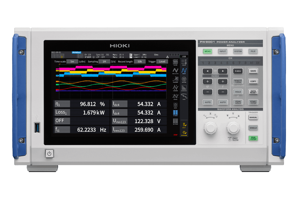
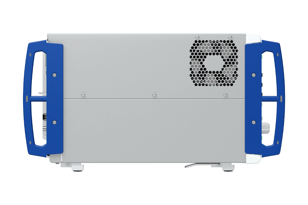
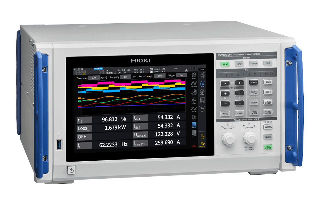
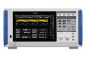
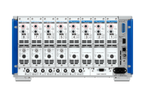
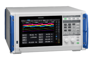
The Hioki PW8001 power analyser is built for that kind of bench. It’s a modular instrument that takes up to eight factory-installed input units, each chosen for what that channel has to measure.
Choose the input unit to match the job
The most important decision when specifying a PW8001 is which input unit goes in which channel. The two options aren’t a good and better version of the same thing. Each one does something the other can’t.
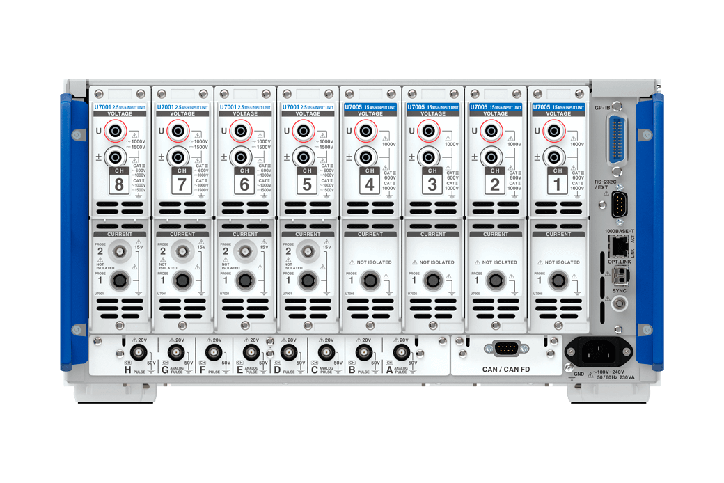
U7005 15 MS/s input unit is for SiC and GaN inverters and for reactor and transformer loss. It samples at 15 MHz with 18-bit resolution, has a measurement band of DC and 0.1 Hz to 5 MHz, and delivers the PW8001’s headline accuracy figures. Voltage safety rating is 600 V CAT III and 1000 V CAT II.
U7001 2.5 MS/s input unit is for high-efficiency IGBT inverters and high-voltage solar inverters. It samples at 2.5 MHz with 16-bit resolution across DC and 0.1 Hz to 1 MHz. It’s the unit to choose for direct measurement up to 1500 V DC, rated at 600 V AC / 1000 V DC CAT III and 1000 V AC / 1500 V DC CAT II, and the only one with a BNC input for current probes and CTs.
The units can be mixed in one mainframe. When they are, the U7005 units occupy the channels starting at CH1, with like units next to each other, and only adjacent units can be combined in the same wiring connection. A typical setup might put U7005 units on an inverter’s output and U7001 units on its high-voltage DC input. Input units are factory-fitted, so they need to be specified when you order.
Accuracy across the whole conversion chain
Efficiency work needs accurate power on both sides of a converter, and those two sides are often at very different frequencies. With the U7005, power accuracy is ±(0.01% of reading + 0.02% of range) at 50/60 Hz, ±(0.02% of reading + 0.03% of range) at DC, ±(0.05% of reading + 0.05% of range) at 10 kHz and ±(0.15% of reading + 0.05% of range) at 50 kHz. Those are the ±0.03%, ±0.05% and ±0.2% figures you’ll see quoted for this instrument.
The U7001 is specified at ±(0.02% of reading + 0.05% of range) at both 50/60 Hz and DC, and ±(0.4% of reading + 0.1% of range) at 50 kHz.
Frequency flatness shows how the inputs hold up well above an inverter’s carrier. On the U7005, amplitude stays within ±0.1% to 300 kHz and phase within ±0.1° to 500 kHz (typical values). Those figures matter because PWM power is spread across the spectrum, and a roll-off in amplitude or phase turns directly into a power error.
All of these figures apply at 23 °C ±3 °C after a 30-minute warm-up and zero adjustment, and current sensor accuracy is added for current and power. That makes the sensor choice part of the accuracy decision.
Holding up against fast switching noise
Fast edges inject common-mode noise straight into the measurement. The U7005’s common-mode rejection is 120 dB or greater at 50/60 Hz and 110 dB typical at 100 kHz. That gives you a cleaner reading on the high side of a half bridge, where the voltage is swinging hardest. The U7001 is specified at 100 dB or greater at 50/60 Hz and 80 dB typical at 100 kHz.
Hioki’s high-accuracy sensors connect through the Probe 1 terminal, which identifies and powers the sensor automatically. Compatible sensors also carry their phase characteristics, so the analyser applies phase correction without manual setup. High-frequency, low-power-factor measurements are where that correction earns its keep.
Finding where high-frequency loss comes from
A single efficiency number tells you that loss exists. Power Spectrum Analysis tells you at what frequency it sits. The PW8001’s FFT function breaks voltage, current and active power down by frequency, up to 6 MHz with the U7005 and 1 MHz with the U7001, on up to three channels at a time. For teams tuning gate drives or comparing switching strategies, it turns a percentage into something you can act on.
Reactor and transformer loss is one of the most demanding jobs in power measurement, because the better the component gets, the lower its power factor becomes. The U7005’s high-frequency performance and noise rejection suit real-operating-condition loss testing on these parts.
Other analysis tools include wideband harmonics to the 500th order, 5 megawords of waveform memory per channel with level and event triggers, and up to 20 user-defined equations. A GPU-based processing engine refreshes the waveform display up to 40 times per second (at 15 MS/s with a 1 kpoint recording length), which makes live tuning far less of a guessing game.
For conformance work, the PW8001 has an IEC measurement mode for harmonics to IEC 61000-4-7, covering the 0th to 200th orders and inter-harmonics, and flicker to IEC 61000-4-15. These run on 50 Hz or 60 Hz lines.
Four motors on one instrument
Motor analysis models (the -1x order codes) can analyse up to four motors simultaneously. That covers dual-motor and all-wheel-drive layouts, and multi-motor drives, on one display. The instrument handles analog DC, frequency and pulse inputs from torque meters and encoders.
Two functions stand out for motor developers:
- Electrical angle measurement supports vector control work in the dq coordinate system, and lets you calculate Ld and Lq for permanent magnet synchronous motors under real operating conditions.
- Torque meter correction applies user-defined nonlinear compensation and friction compensation tables, reducing a source of error that can dominate when you’re evaluating high-efficiency motors.
From eight channels to thirty-two
Eight power channels in a single instrument covers most inverter and drive testing. When it doesn’t, there are two ways to scale.
- Optical link (order codes -04, -05, -06, -14, -15 and -16) connects two PW8001 units so one instrument can display, calculate and record all 16 channels and up to 8 motors. Multi-mode fibre can run up to 500 m, which helps with spreading measurement points around a large test cell.
- BNC synchronisation ties up to four units together for 32 channels. Settings are operated from the primary unit, and integration, data refresh and clock are aligned. Each unit stores its own data, ready to combine on one time base.
Neither sync method can be used at data update rates of 10 ms or less, and they can’t be used at the same time. The optical link also doesn’t support IEC measurement mode on the primary unit, and CAN output isn’t available while it’s in use.
Fits into your test system
Standard interfaces are gigabit LAN, GP-IB, RS-232C, USB flash drive, external control and BNC sync. Factory options add 20 channels of D/A output (-02, -05, -12, -15) or CAN/CAN FD output (-03, -06, -13, -16). Data is saved to a USB flash drive, as the PW8001 doesn’t have internal data storage. Modbus/TCP, a LabVIEW driver and a MATLAB toolkit make it straightforward to bring into an automated bench, and Hioki’s GENNECT software covers logging and analysis on a PC.
High-voltage testing: know the limits
Solar and storage systems keep moving to higher DC voltages. The U7001 accepts up to 1000 V AC, 1500 V DC or ±2000 V peak directly, with a maximum rated line-to-ground voltage of 600 V AC / 1000 V DC CAT III and 1000 V AC / 1500 V DC CAT II. Between 1000 V DC and 1500 V DC, add 0.045% of reading to voltage and active power accuracy. Hioki gives these as design figures, and offers special-order calibration of the U7001 where accuracy needs to be guaranteed in that band.
The U7005 has a maximum input of 1000 V, ±2000 V peak, and derates at high frequency, to (1300 − f) V between 400 kHz and 1 MHz and to 200 V from 1 MHz to 5 MHz. Its rating is 600 V CAT III and 1000 V CAT II. For higher voltages, the optional VT1005 high-voltage divider extends measurement to 5000 V.
Who the PW8001 suits
- Inverter and motor R&D teams working with SiC and GaN devices
- EV powertrain developers evaluating dual inverters and multi-motor drives
- Solar inverter and power conditioner engineers working to 1500 V DC
- Magnetics designers measuring reactor and transformer loss
- Rail, aerospace, marine and industrial drive teams measuring parallel inverters
- Universities and research labs running high-accuracy efficiency studies
Getting the configuration right with Rapid-Tech
With two input unit types, twelve order codes and more than twenty compatible current sensors, a PW8001 specification is worth talking through before you commit. Our team can help you work out the channel mix, sensor bandwidth and interface options for your test plan, then put together a complete quote for Australian delivery. Request a quote and tell us what you’re measuring.
U7001 or U7005: Input Unit Comparison
| U7005 15 MS/s | U7001 2.5 MS/s | |
|---|---|---|
| Best suited to | SiC/GaN inverters, reactor and transformer loss | IGBT inverters, high-voltage solar inverters |
| Sampling | 15 MHz, 18-bit | 2.5 MHz, 16-bit |
| Measurement band | DC, 0.1 Hz to 5 MHz | DC, 0.1 Hz to 1 MHz |
| Power accuracy, 50/60 Hz | ±(0.01% rdg + 0.02% rng) | ±(0.02% rdg + 0.05% rng) |
| Power accuracy, DC | ±(0.02% rdg + 0.03% rng) | ±(0.02% rdg + 0.05% rng) |
| Power accuracy, 10 kHz | ±(0.05% rdg + 0.05% rng) | ±(0.2% rdg + 0.05% rng) |
| Power accuracy, 50 kHz | ±(0.15% rdg + 0.05% rng) | ±(0.4% rdg + 0.1% rng) |
| CMRR, 50/60 Hz | 120 dB or greater | 100 dB or greater |
| CMRR, 100 kHz | 110 dB typical | 80 dB typical |
| Maximum input voltage | 1000 V, ±2000 V peak (derates above 400 kHz) | 1000 V AC, 1500 V DC, ±2000 V peak |
| Maximum rated line-to-ground voltage | 600 V CAT III; 1000 V CAT II (anticipated transient overvoltage 6000 V) | 600 V AC / 1000 V DC CAT III; 1000 V AC / 1500 V DC CAT II (anticipated transient overvoltage 8000 V) |
| Current inputs | Probe 1 (ME15W) | Probe 1 (ME15W), Probe 2 (BNC) |
| FFT analysis range | DC to 6 MHz | DC to 1 MHz |
Model Variants
| Order code | Motor analysis | D/A output | CAN / CAN FD | Optical link |
|---|---|---|---|---|
| PW8001-01 | – | – | – | – |
| PW8001-02 | – | ✔ | – | – |
| PW8001-03 | – | – | ✔ | – |
| PW8001-04 | – | – | – | ✔ |
| PW8001-05 | – | ✔ | – | ✔ |
| PW8001-06 | – | – | ✔ | ✔ |
| PW8001-11 | ✔ | – | – | – |
| PW8001-12 | ✔ | ✔ | – | – |
| PW8001-13 | ✔ | – | ✔ | – |
| PW8001-14 | ✔ | – | – | ✔ |
| PW8001-15 | ✔ | ✔ | – | ✔ |
| PW8001-16 | ✔ | – | ✔ | ✔ |
Included: power cord, instruction manual, D-sub 25-pin connector (-02, -05, -12, -15).
Required and ordered separately: input units (U7001 and/or U7005, specified at order and factory-installed), voltage cords and current sensors.
Technical Specifications
| Specification | Value | Why It Matters |
|---|---|---|
| Power channels | 1 to 8, using U7001 and/or U7005 units (mixed configurations available) | Buy the channels and performance the bench needs |
| Measurement lines | 1P2W, 1P3W, 3P3W, 3P4W | Covers single-phase through three-phase four-wire systems |
| Frequency band | U7005: DC, 0.1 Hz to 5 MHz; U7001: DC, 0.1 Hz to 1 MHz (−3 dB typical) | Reaches the switching content of fast power devices |
| Frequency flatness (typical) | U7005: ±0.1% to 300 kHz, ±0.1° to 500 kHz; U7001: ±0.1% to 100 kHz, ±0.1° to 300 kHz | Limits power error from high-frequency roll-off |
| Sampling | U7005: 15 MHz, 18-bit; U7001: 2.5 MHz, 16-bit | Resolves fast edges and small signals |
| Basic power accuracy, 50/60 Hz | U7005: ±(0.01% rdg + 0.02% rng); U7001: ±(0.02% rdg + 0.05% rng) | Grid-side and fundamental accuracy |
| Power accuracy, DC | U7005: ±(0.02% rdg + 0.03% rng); U7001: ±(0.02% rdg + 0.05% rng) | Critical for battery and DC link measurement |
| Power accuracy, 50 kHz | U7005: ±(0.15% rdg + 0.05% rng); U7001: ±(0.4% rdg + 0.1% rng) | Accuracy where switching-related power sits |
| Accuracy conditions | 23 °C ±3 °C, 80% RH or less, 30 min warm-up; 6-month guarantee (reading error ×1.5 for 1 year) | Starting point for an uncertainty budget; add sensor accuracy |
| Data update rate | 1, 10, 50, 200 ms (averaging and user-defined calculations unavailable at 1 ms) | Tracks fast transients or steady-state averages |
| Voltage ranges | 6, 15, 30, 60, 150, 300, 600, 1500 V | Low-level signals through to high-voltage DC buses |
| Maximum input voltage | U7005: 1000 V, ±2000 V peak; U7001: 1000 V AC, 1500 V DC, ±2000 V peak | Determines which unit suits high-voltage work |
| Maximum rated line-to-ground voltage | U7005: 600 V CAT III, 1000 V CAT II (6000 V transient); U7001: 600 V AC / 1000 V DC CAT III, 1000 V AC / 1500 V DC CAT II (8000 V transient) | Sets where each unit can safely be connected |
| Current ranges | Probe 1: 40 mA to 2 kA by sensor; Probe 2 (U7001): 100 mA to 50 kA by input rate | Scales with sensor choice |
| Common-mode rejection | U7005: 120 dB or greater at 50/60 Hz, 110 dB typical at 100 kHz; U7001: 100 dB or greater at 50/60 Hz, 80 dB typical at 100 kHz | Keeps fast common-mode noise out of the reading |
| Phase correction | Automatic with compatible Hioki sensors | Protects high-frequency, low-power-factor accuracy |
| Harmonics | Wideband mode to 500th order | Detailed distortion analysis |
| IEC measurement mode | IEC 61000-4-7 harmonics (0th to 200th) and IEC 61000-4-15 flicker | Standards-based power quality evaluation |
| FFT / Power Spectrum Analysis | U, I, P; up to 3 channels; DC to 6 MHz (U7005), DC to 1 MHz (U7001) | Pinpoints loss by frequency |
| Waveform recording | 5 megawords per channel; level and event triggers | Captures switching detail and intermittent events |
| Motor analysis (-1x models) | Up to 4 motors; voltage, torque, RPM, frequency, slip, motor power | Multi-motor drive efficiency on one instrument |
| Synchronisation | Optical link: 2 units, 16 channels; BNC: 4 units, 32 channels (neither at 10 ms or less) | Scales to larger systems |
| Interfaces | Gigabit LAN, GP-IB, RS-232C, USB flash drive, external control, BNC sync | Integrates with new and legacy test systems |
| Interface options | D/A 20 channels; CAN or CAN FD; optical link (by order code) | Add only what the system needs |
| Display | 10.1-inch WXGA colour TFT LCD touchscreen | Clear viewing for dense multi-channel data |
| Operating temperature | 0 °C to 40 °C, 80% RH or less, non-condensing | Laboratory and test cell conditions |
| Storage temperature | −10 °C to 50 °C, 80% RH or less, non-condensing | Storage and transport planning |
| Operating environment | Indoors at an elevation of up to 2000 m in a Pollution Level 2 environment; IP20 | Confirms the intended installation conditions |
| Power supply | 100–240 V AC, 50/60 Hz, 230 VA max | Suits Australian mains |
| Dimensions and weight | Approx. 430 × 221 × 361 mm, approx. 14 kg with units mounted | Bench or rack-mount instrument |
| Safety and EMC standards (manufacturer stated) | EN 61010; EN 61326 Class A | Manufacturer’s declared design standards |
| Product warranty (manufacturer stated) | 3 years | Long-term support for a capital purchase; sensor terms vary |
What is the Hioki PW8001?
The Hioki PW8001 is a modular bench power analyser for motor and inverter efficiency analysis. It holds up to eight U7001 or U7005 input units, reaches a 5 MHz band and 15 MHz, 18-bit sampling with the U7005, and analyses up to four motors on motor analysis models.
What is the accuracy of the Hioki PW8001?
With the U7005 input unit, the PW8001’s power accuracy is ±(0.01% of reading + 0.02% of range) at 50/60 Hz, ±(0.02% + 0.03%) at DC and ±(0.15% + 0.05%) at 50 kHz. With the U7001, it’s ±(0.02% + 0.05%) at 50/60 Hz and DC. Current sensor accuracy is added.
Should I choose the U7001 or U7005 input unit?
Choose the U7005 for SiC and GaN inverters, reactors and transformers, where 15 MHz sampling, a 5 MHz band and high common-mode rejection matter. Choose the U7001 for IGBT inverters and solar inverters, or for direct measurement above 1000 V DC, as it’s rated to 1500 V DC CAT II.
How many channels can the Hioki PW8001 measure?
One PW8001 measures up to 8 power channels. Two units connected by optical link can consolidate 16 channels and 8 motors on one instrument, and four units connected by BNC synchronisation provide 32 time-aligned channels. Neither link works at data update rates of 10 ms or less.
What is the maximum voltage of the Hioki PW8001?
It depends on the input unit. The U7001 accepts 1000 V AC or 1500 V DC directly, rated 600 V AC / 1000 V DC CAT III and 1000 V AC / 1500 V DC CAT II. The U7005 accepts 1000 V, rated 600 V CAT III and 1000 V CAT II.
What is Power Spectrum Analysis on the PW8001?
Power Spectrum Analysis uses FFT to break voltage, current and active power down by frequency, so engineers can see where high-frequency power loss occurs. On the PW8001 it reaches 6 MHz with the U7005 input unit and 1 MHz with the U7001, on up to three channels.
Frequently Asked Questions
Does the PW8001 include input units and current sensors?
No. Input units, voltage cords and current sensors are needed for measurement and are ordered separately. Input units are factory-installed, so they must be specified at the time of ordering.
Can U7001 and U7005 input units be mixed in one PW8001?
Yes, up to eight units in total. When units are mixed, the U7005 units occupy CH1 onwards with like units next to each other. Only adjacent units can be used in the same wiring connection.
Which PW8001 models include motor analysis?
The PW8001-11 through PW8001-16 include motor analysis, with up to four motors analysed simultaneously. Models PW8001-01 through -06 don’t include it.
Is the PW8001 suitable for 1500 V solar inverter testing?
Yes, when fitted with U7001 input units, which are rated 1000 V AC / 1500 V DC CAT II and 600 V AC / 1000 V DC CAT III. Between 1000 V DC and 1500 V DC, an extra 0.045% of reading applies as a design figure, and special-order calibration can guarantee accuracy in that band.
Can the PW8001 do IEC harmonic and flicker measurement?
Yes. IEC measurement mode covers harmonics to IEC 61000-4-7 and flicker to IEC 61000-4-15 on 50 Hz and 60 Hz lines. Harmonics are analysed from the 0th to the 200th order, along with inter-harmonics.
Can I have D/A output and CAN on the same PW8001?
No. The order codes offer D/A output or CAN/CAN FD, not both. Either can be combined with motor analysis or the optical link, depending on the model.
Can current probes with BNC output be used with the PW8001?
Yes, on the U7001. Its BNC Probe 2 input connects sensors with BNC output terminals, such as a current probe or CT. An additional ±(0.05% of reading + 0.2% of range) applies to current and active power accuracy when using Probe 2. The U7005 only has the Probe 1 connector for Hioki sensors.
Where does the PW8001 save measurement data?
Measurement data, waveforms and screenshots save to a USB flash drive. Settings and some configuration files can also go to an FTP server. Data can also be collected over LAN using Hioki’s PC software.
What operating conditions does the PW8001 need?
The PW8001 operates from 0 °C to 40 °C at 80% RH or less without condensation. Hioki specifies it for use indoors at an elevation of up to 2000 m in a Pollution Level 2 environment, with IP20 protection.
What warranty applies to the Hioki PW8001?
Hioki lists a 3-year product warranty for the PW8001. Warranty periods for accessories vary, including 1 year for the CT6833, CT6834 and CT6847A sensors. Contact us to confirm the terms for your purchase.




Reviews
There are no reviews yet.