
 Promotions



Why good power data is hard to get outside the lab
Most serious efficiency work ends up in one of two compromises. You either haul the test article to a bench analyser, or you take a lighter instrument to the test article and accept that the numbers won’t stand up to scrutiny.
That compromise gets expensive quickly. EV range testing happens in climatic chambers and on real roads. DC-DC converter efficiency gains are now argued over in tenths of a percent. Production lines need a figure they can defend, and they rarely have room for a full-size bench instrument at every station. A power meter that loses accuracy when the chamber drops, can’t read the vehicle’s own data, or needs mains power in a moving car leaves you stitching results together afterwards.
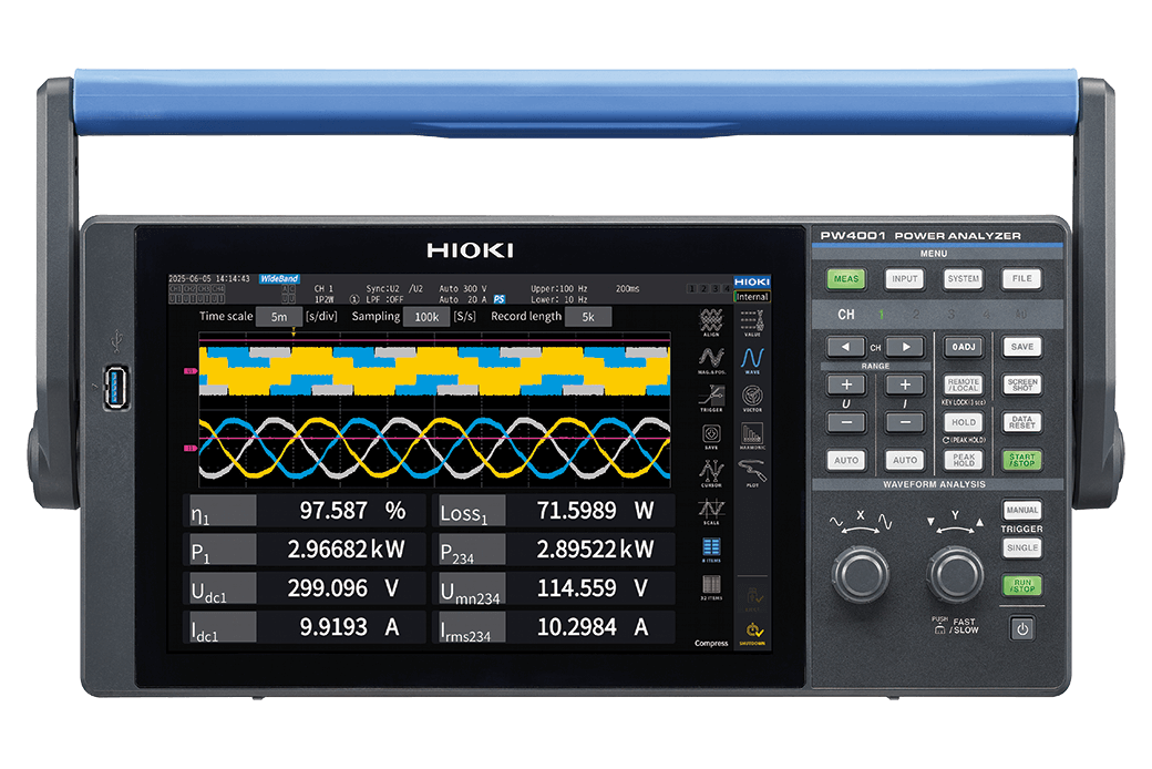
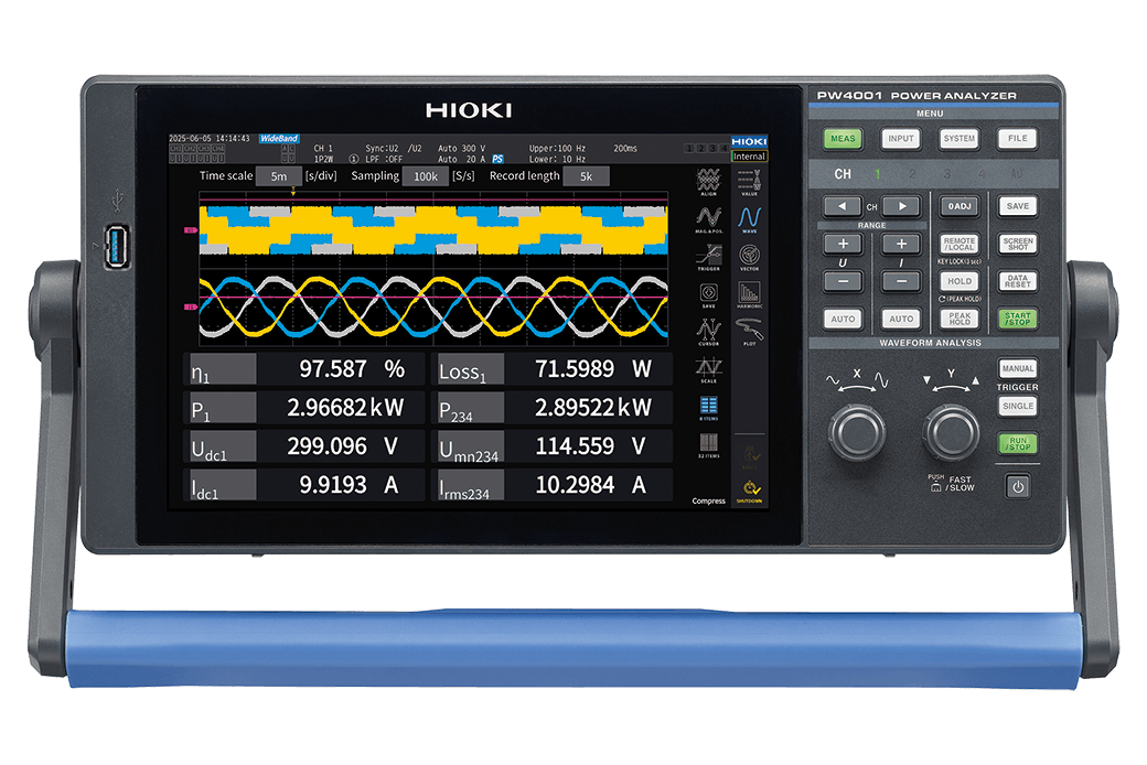
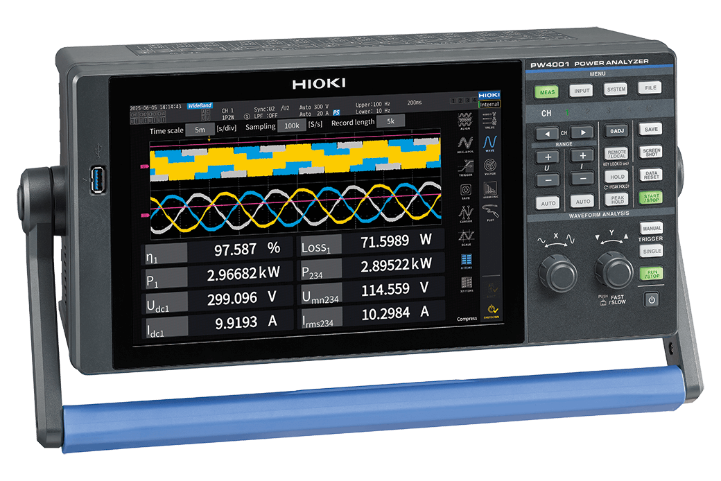
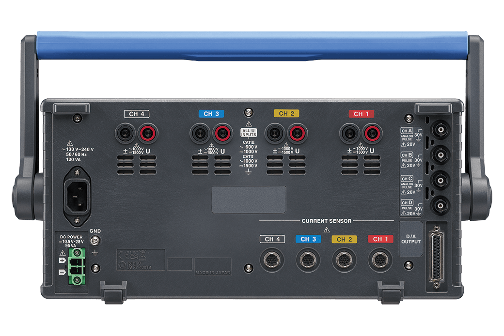
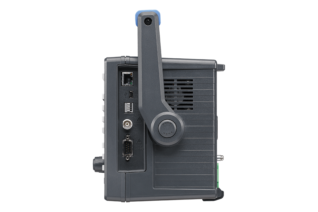
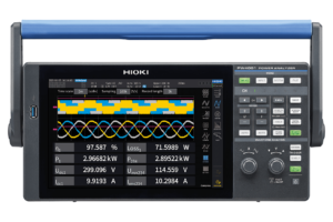
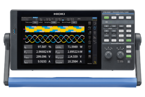
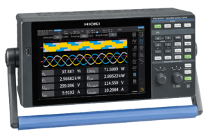
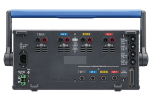
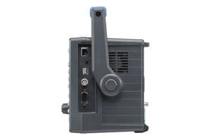
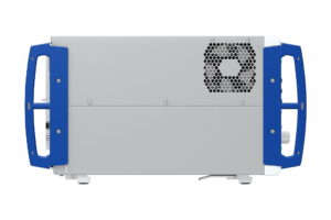
The Hioki PW4001 power analyser was designed to close that gap. It puts four isolated voltage and four isolated current channels into a 361 × 176 × 135 mm package weighing 4.6 kg, with a 360° carry handle, and it’s specified for the places bench analysers don’t go.
Accuracy you can quote, with the conditions stated
The PW4001’s headline figure is ±0.04% at DC and 50/60 Hz. In datasheet terms, that’s ±(0.03% of reading + 0.01% of range) for active power, voltage and current. At 10 kHz the power specification is ±(0.2% of reading + 0.05% of range), and at 50 kHz it’s ±(0.4% of reading + 0.1% of range).
Those figures apply at 23 °C ±3 °C after a 30-minute warm-up and zero adjustment, and they apply to the analyser alone. For current and active power, the current sensor’s accuracy gets added. Hioki puts the combined basic accuracy within ±0.1% with through-type sensors and within ±0.3% with high-accuracy clamp sensors such as the CT683x and CT684x series, with some exceptions listed in the datasheet. That’s the number to use when you’re writing a test plan.
Bandwidth runs from DC and 0.1 Hz to 600 kHz (−3 dB typical), with published accuracy figures up to 200 kHz. Inverters switching at 10 kHz to 20 kHz produce harmonic energy well above the carrier, so that headroom matters for honest loss measurement. Sampling is 16-bit at 2.5 MHz, simultaneous on voltage and current.
Clamp and pass-through sensors also bring phase error, and at high frequency and low power factor it can swamp everything else. The PW4001 corrects for this automatically when you use a compatible Hioki sensor, drawing on the characteristics recorded for that sensor at the factory. You plug in, and the correction is applied without a manual phase table.
Catching what a 200 ms meter averages away
Motors and inverters do their most interesting work in milliseconds. The PW4001 offers data update rates of 1 ms, 10 ms, 50 ms and 200 ms, so torque steps, regen transitions and control-loop behaviour show up as events instead of disappearing into an average. At the 1 ms setting, add ±0.1% of range to voltage, current and active power accuracy, and note that averaging and user-defined calculations aren’t available.
Efficiency calculation also follows the direction of energy flow. The instrument detects charge and discharge, and motoring and regeneration, then switches its calculation accordingly. That stops the familiar nonsense of efficiency figures above 100% during regenerative braking.
Built for EV range and energy consumption testing
WLTP low-temperature testing happens at −7 °C, and that’s where a lot of instruments have to sit outside the chamber on long leads. The PW4001 has an operating range of −20 °C to 50 °C, so it can be installed in the chamber, close to the vehicle. Hioki specifies its DC and 50/60 Hz accuracy as meeting WLTP and SAE J1634 requirements, which supports type-approval-style energy consumption and range work.
Two practical conditions apply. Hioki states: “If used at temperatures below 0°C (32°F), warm up in a 0°C to 50°C (32°F to 122°F) environment prior to use.” Outside the 23 °C ±3 °C band, a temperature coefficient of ±0.005% of reading per °C applies.
Engine bays and battery packs are cramped, so sensor choice counts too. The slim CT6833 (200 A) and CT6834 (500 A) clamp probes are designed for that wiring, with ±0.07% of reading ±0.007% f.s. amplitude accuracy at 50/60 Hz and an operating range down to −45 °C.
Battery voltage without touching the high-voltage bus
Connecting voltage leads to a vehicle’s HV system takes time, adds risk and sometimes isn’t allowed. The traditional workaround was to pull battery voltage from the BMS over CAN, then merge it with the current data by hand after the test.
The PW4001 acquires voltage over CAN or CAN FD while it measures current, and calculates power in real time on a common time base. Via the OBD-II port it supports ISO 15765-2 diagnostic communication and can log up to 6 diagnostic IDs using SAE J1979 and J1979-2 parameters. Direct CAN input can log up to 20 IDs, so speed, distance or gear status can sit alongside your power data. Where a signal isn’t exposed at OBD-II, the optional SP7001-95 non-contact CAN sensor clips over the wire insulation and picks it up without cutting into the loom.
Measured values can also go out onto CAN, which makes it simpler to bring power data into existing CAN analysis tools.
On-road testing without an inverter in the boot
The PW4001-04 and PW4001-05 add an external DC supply input that runs from 10.5 V to 28 V, so the analyser can be powered from a 12 V or 24 V vehicle system. Vibration resistance is specified to JIS D 1601 Type 1 passenger car conditions (45 m/s², 4.6 G).
Plan DC-powered installs around the datasheet limits. The full 10.5 V to 28 V range applies from −20 °C to 40 °C, and from 40 °C to 50 °C the supply is limited to 10.5 V to 20 V. Large sensors can also reduce the connection count: only three CT6877A, CT6876A or CT6904A series sensors can be connected under certain temperature and supply combinations. Hioki’s environmental rating is “Indoor use, pollution level 2, altitude up to 2000 m”, so check that your installation suits it.
Production and DC-DC converter testing
On a line, a number proves conformance and a waveform explains a failure. The PW4001 gives you both. It records up to 5 megawords of voltage, current or motor waveform, which is 2 seconds at the full 2.5 MS/s or 50 seconds at 100 kS/s, with level and event triggers, zoom and cursors. Sixteen-bit resolution makes it possible to see fine ripple riding on a DC bus.
Direct voltage input reaches 1000 V AC and 1500 V DC, so 800 V DC architectures can be measured without differential probes. The voltage safety rating is 600 V AC / 1000 V DC CAT III and 1000 V AC / 1500 V DC CAT II. For higher voltages, the optional VT1005 divider extends measurement to 5000 V.
That combination suits battery energy storage work, including data centre backup systems where a 0.1% efficiency change has real cost attached, along with AC-DC converters and high-voltage power conditioners.
More depth when the job calls for it
- Harmonics: wideband analysis to the 500th order. The PW9006 licence adds IEC 61000-4-7 harmonic and IEC 61000-4-15 flicker measurement for firmware V1.10 or later.
- Motors: the PW4001-03 and -05 analyse up to two motors from torque and speed sensors, including slip and motor power.
- Custom maths: up to 20 user-defined formulas run in real time, useful for id/iq conversion and operating Ld/Lq values.
- Analog output: the PW4001-02 and -05 provide 16 channels of D/A output, with waveform output at 1 MHz, for feeding external loggers.
- More points: up to eight units synchronise over BNC for 32 channels. Primary and secondary units need matching settings, and synchronisation isn’t available at data update intervals of 10 ms or less.
A 10.1-inch WXGA touchscreen, on-screen wiring guide and one-touch signal type settings reduce setup mistakes. Data saves to 15 GB of internal memory or a USB flash drive. LAN (1000BASE-T) supports SCPI commands, Modbus/TCP and XCP on Ethernet, while LabVIEW and MATLAB drivers and Hioki’s GENNECT software cover automation and analysis.
Who the PW4001 suits
- EV and hybrid engineering teams running range, energy consumption and real-driving tests
- Motor and inverter developers on dynamometer test benches
- Battery, ESS and DC-DC converter developers and manufacturers
- Solar and power conditioner engineers working up to 1500 V DC
- Universities, TAFEs and research groups that need one instrument across several labs
- Production test engineers needing a compact, defensible efficiency measurement
Why buy through Rapid-Tech
A power analyser is only as good as the sensors, leads and options specified with it. Our team can help you match current sensors to your frequency range and conductor size, choose the right PW4001 variant and put together a complete quote for Australian delivery. Tell us what you’re testing and we’ll help you get the setup right. Request a quote to get started.
Model Variants
| Order code | Standard functions | D/A output | Motor analysis | External DC power (10.5–28 V) |
|---|---|---|---|---|
| PW4001-01 | 4 channels, 15 GB memory, CAN interface | – | – | – |
| PW4001-02 | As above | ✔ | – | – |
| PW4001-03 | As above | – | ✔ | – |
| PW4001-04 | As above | – | – | ✔ |
| PW4001-05 | As above | ✔ | ✔ | ✔ |
Included: startup guide, power cord, USB cable L1003, D-sub connector (-02, -05), DC power supply connector (-04, -05).
Ordered separately: current sensors, voltage cords, PW9006 IEC licence, SP7001-95 CAN sensor, C4001 carrying case and rack fittings.
Technical Specifications
| Specification | Value | Why It Matters |
|---|---|---|
| Channels | 4 voltage, 4 current, isolated between channels | Measures three-phase input plus a DC side, or four separate circuits |
| Measurement lines | 1P2W, 1P3W, 3P3W, 3P4W | Covers single-phase through three-phase four-wire systems |
| Frequency band | DC, 0.1 Hz to 600 kHz (−3 dB typical) | Captures harmonic content well above inverter carrier frequencies |
| Published accuracy range | DC to 200 kHz | Check this limit when budgeting uncertainty at high frequency |
| Power accuracy, DC and 50/60 Hz | ±(0.03% rdg + 0.01% rng) | Resolves small efficiency differences; add current sensor accuracy |
| Power accuracy, 10 kHz | ±(0.2% rdg + 0.05% rng) | Relevant to fundamental and switching-related content in converters |
| Power accuracy, 50 kHz | ±(0.4% rdg + 0.1% rng) | Supports high-frequency converter evaluation |
| Accuracy conditions | 23 °C ±3 °C, 80% RH or less, 30 min warm-up, after zero adjustment | The basis your uncertainty budget needs to start from |
| Sampling | 16-bit, 2.5 MHz | Resolves switching events and fine DC ripple |
| Data update rate | 1, 10, 50, 200 ms (at 1 ms add ±0.1% rng; no averaging or UDF) | Captures fast power transients |
| Voltage ranges | 6, 15, 30, 60, 150, 300, 600, 1500 V | Low ranges suit auxiliary rails; the top range suits HV buses |
| Maximum input voltage | 1000 V AC, 1500 V DC, ±2000 V peak | Direct connection to high-voltage DC systems |
| Maximum rated line-to-ground voltage | 600 V AC / 1000 V DC CAT III; 1000 V AC / 1500 V DC CAT II (anticipated transient overvoltage 8000 V) | Sets where the instrument can safely be connected |
| Current ranges | 40 mA to 2000 A depending on sensor; to 8000 A with CT9557 summing | One analyser scales from small signals to multi-cable feeders |
| Current input | Hioki ME15W sensor connector, automatic sensor recognition | Faster setup and fewer scaling errors |
| Phase correction | Automatic with compatible Hioki sensors | Protects accuracy at high frequency and low power factor |
| Common-mode rejection | 80 dB or more at 50/60 Hz | Reduces error from high common-mode voltages |
| Harmonics | Wideband mode to 500th order; IEC harmonics and flicker via PW9006 | Detailed analysis, with a licence path to standards-based testing |
| Waveform recording | 5 megawords, level and event triggers | Keeps the evidence behind the number |
| Motor analysis (-03, -05) | Up to 2 motors; torque, RPM, frequency, slip, motor power | Mechanical and electrical efficiency in one instrument |
| D/A output (-02, -05) | 16 channels; waveform output 1 MHz | Feeds loggers and external systems |
| CAN | CAN / CAN FD input and output, OBD-II diagnostic acquisition | Voltage and vehicle signals without HV probing |
| Interfaces | LAN (1000BASE-T), USB 2.0 function, USB flash, external control, BNC sync, CAN/CAN FD | Fits automated and standalone test setups |
| Multi-unit sync | Up to 8 units, 32 channels (not at update intervals of 10 ms or less) | Scales to whole-vehicle power mapping |
| Internal memory | 15 GB | Local storage for settings, data and screenshots |
| Display | 10.1-inch WXGA colour TFT LCD touchscreen | Dense data remains readable and easy to navigate |
| Operating temperature | −20 °C to 50 °C, 80% RH or less, non-condensing (warm up at 0 °C to 50 °C before use below 0 °C) | Can be installed inside climatic chambers |
| Operating environment | Indoor use, pollution level 2, altitude up to 2000 m | Confirms the intended installation conditions |
| Vibration | JIS D 1601 Type 1 equivalent, 45 m/s² (4.6 G) | Specified for passenger vehicle vibration |
| Power supply | 100–240 V AC, 50/60 Hz, 120 VA max; 10.5–28 V DC, 95 VA max (-04, -05) | Mains on the bench, vehicle DC on the road |
| Dimensions and weight | 361 × 176 × 135 mm, approx. 4.6 kg | Portable enough to move between test sites |
| Safety and EMC standards (manufacturer stated) | EN 61010; EN 61326 Class A | Manufacturer’s declared design standards |
| Product warranty (manufacturer stated) | 3 years | Long-term support for a capital purchase; sensor terms vary |
What is the Hioki PW4001?
The Hioki PW4001 is a portable four-channel power analyser for EV, motor, inverter, battery and DC-DC converter testing. It weighs 4.6 kg, measures from DC to a 600 kHz band, is specified to ±0.04% at DC and 50/60 Hz, and operates from −20 °C to 50 °C.
How accurate is the Hioki PW4001?
The PW4001’s power accuracy at DC and 50/60 Hz is ±(0.03% of reading + 0.01% of range), commonly quoted as ±0.04%. Current sensor accuracy is added for current and power. Hioki states combined basic accuracy within ±0.1% with through-type sensors and ±0.3% with high-accuracy clamps, with some exceptions.
Can the PW4001 be used for WLTP and SAE J1634 EV testing?
Yes. Hioki specifies the PW4001’s DC and 50/60 Hz accuracy as meeting WLTP and SAE J1634 requirements, and it operates down to −20 °C for installation in a −7 °C test chamber. If it’s used below 0 °C, it must first be warmed up in a 0 °C to 50 °C environment.
Can the PW4001 measure EV power without connecting to high voltage?
Yes, using vehicle data for the voltage input. The PW4001 acquires battery voltage over CAN or the OBD-II port, measures current with a clamp sensor, and calculates power in real time. Measuring current still requires safe access to the conductor and a suitably rated sensor.
What’s the difference between the PW4001-01 to PW4001-05?
All five PW4001 models have four channels, 15 GB of memory and a CAN interface. The -01 is the base model, the -02 adds D/A output, the -03 adds motor analysis and the -04 adds a 10.5 V to 28 V DC supply input. The -05 includes all three options.
What is the maximum voltage of the Hioki PW4001?
The PW4001 accepts direct input up to 1000 V AC and 1500 V DC, or ±2000 V peak. Its maximum rated line-to-ground voltage is 600 V AC / 1000 V DC CAT III and 1000 V AC / 1500 V DC CAT II. The optional VT1005 divider extends measurement to 5000 V.
Frequently Asked Questions
Does the Hioki PW4001 come with current sensors and voltage leads?
No. Current sensors and voltage cords are ordered separately so you can match them to your current level, frequency range and conductor size. The analyser ships with a startup guide, power cord and USB cable, plus connectors on models with the relevant options.
Which PW4001 model can run from a vehicle’s 12 V or 24 V supply?
The PW4001-04 and PW4001-05 have the external DC power input, rated 10.5 V to 28 V. Between 40 °C and 50 °C, the rated supply range is limited to 10.5 V to 20 V.
Can the PW4001 be left inside a cold chamber during testing?
Its operating range of −20 °C to 50 °C allows installation in a chamber, including at the −7 °C used for WLTP low-temperature testing. Below 0 °C, Hioki requires a warm-up in a 0 °C to 50 °C environment before use, and a temperature coefficient applies to accuracy.
Which PW4001 models include motor analysis?
The PW4001-03 and PW4001-05 include motor analysis for up to two motors. Torque can be taken from voltage or frequency signals, and speed from pulse or frequency signals.
Can multiple PW4001 analysers be synchronised?
Yes. Up to eight units can be synchronised over BNC for 32 measurement channels. All units need the same measurement mode and data update interval, and synchronisation isn’t available at data update intervals of 10 ms or less.
Does the PW4001 measure IEC harmonics and flicker?
Wideband harmonic analysis to the 500th order is built in. IEC 61000-4-7 harmonic and IEC 61000-4-15 flicker measurement are added with the PW9006 licence, which requires PW4001 firmware V1.10 or later.
Is the PW4001 suitable for use in a moving vehicle?
Hioki designs the PW4001 for real-driving tests, with DC power on the -04 and -05 and specified passenger vehicle vibration resistance. Its stated operating environment is indoor use, pollution level 2, up to 2000 m altitude, so the installation should keep it within those conditions.
How does the PW4001 compare with the Hioki PW3390?
Hioki’s specifications show the PW4001 extending the band from 200 kHz to 600 kHz, sampling at 2.5 MHz instead of 500 kHz, and tightening DC accuracy to ±(0.03% rdg + 0.01% rng). It also adds a 1 ms update rate, CAN and a touchscreen at the same 4.6 kg weight.
What software works with the PW4001?
Hioki offers GENNECT One, GENNECT Space, PW Data Receiver and CAN Editor as free downloads, along with LabVIEW drivers and a MATLAB toolkit. The instrument also supports SCPI commands, Modbus/TCP and XCP on Ethernet over LAN.
What warranty applies to the Hioki PW4001?
Hioki lists a 3-year product warranty for the PW4001. Warranty periods for accessories vary, including 1 year for the CT6833, CT6834 and CT6847A sensors. Contact us to confirm the terms for your purchase.



Reviews
There are no reviews yet.