


Fluke FEV350 EV Charging Station Analyzer – Professional AC EVSE Tester for Type 1 & Type 2 Chargers
The Challenge: Testing EV Infrastructure Demands Purpose-Built Tools
Australia’s electric vehicle charging network is expanding rapidly, with thousands of new charging stations appearing in commercial premises, residential complexes, and public spaces each year. Every one of these installations requires rigorous safety testing and ongoing verification to protect users and meet regulatory requirements.
Traditional electrical testing equipment wasn’t designed for EVSE-specific measurements. Control pilot signal analysis, RCD-DD fault current testing, and simulated vehicle state verification all require specialised functionality that general-purpose testers simply cannot provide.
The consequences of inadequate EVSE testing extend beyond compliance failures. Faulty charging stations create genuine safety hazards—from shock risks to fire dangers. For contractors responsible for commissioning and maintaining EV infrastructure, incomplete testing exposes both users and businesses to unacceptable liability.
A Complete EVSE Testing Solution in Your Hand
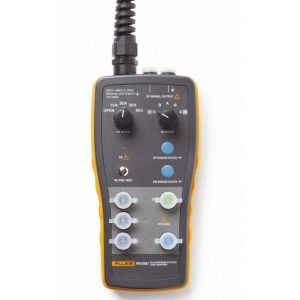
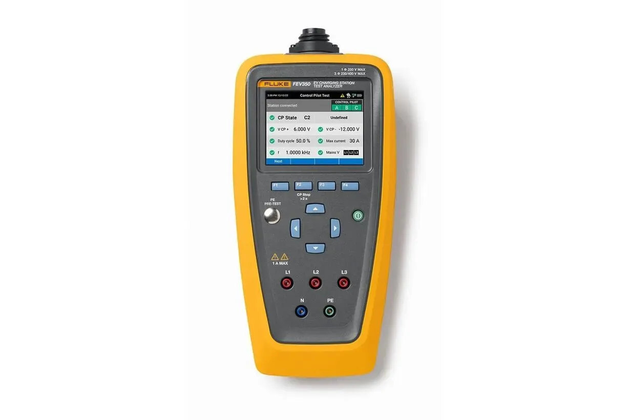
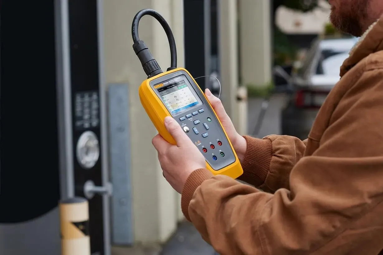
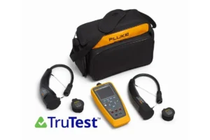
The Fluke FEV350 consolidates everything needed for comprehensive AC charging station verification into a single, portable analyser. Rather than juggling multiple instruments and piecing together results, technicians work through guided test sequences that cover every critical safety and performance parameter.
From the moment you connect to a Type 1 or Type 2 charging socket, the FEV350 begins verifying safe operating conditions. The protective earth pre-test confirms no dangerous voltages exist before proceeding, then automated sequences guide you through RCD trip testing, control pilot analysis, proximity pilot verification, and fault simulation.
Expert Mode eliminates instructional prompts for experienced users who want to move quickly through familiar workflows. Auto-Sequence functionality runs all sub-tests within each measurement category at the push of a button, dramatically reducing time on site while ensuring nothing gets missed.
When paired with compatible Fluke multifunction installation testers via Bluetooth 5.0, the FEV350 extends its capabilities to include earth bond, insulation resistance, and loop impedance measurements—providing complete electrical installation verification without additional equipment.
Key Capabilities That Matter on Australian Job Sites
Comprehensive RCD/RDC-DD Testing Modern EV charging stations incorporate sophisticated residual current protection beyond standard RCDs. The FEV350 tests both conventional 30mA RCD trip response and the 6mA DC sensitive RDC-DD protection specifically required for EVSE applications. You’ll verify trip times across multiple test currents—x0.5, x1, and x5 multipliers—with both fixed-current and ramping trip current modes. Support for Type A, Type B/B+, and RDC-PD devices ensures compatibility with virtually any installed protection scheme.
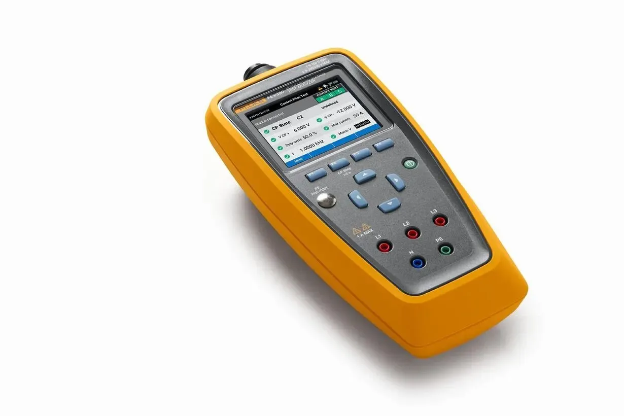
Control Pilot Signal Analysis with Waveform Capture The communication between charging station and vehicle depends on precise control pilot signalling. The FEV350 measures CP voltage levels, PWM duty cycle, and signal frequency with laboratory-grade accuracy, then displays captured waveforms for visual verification. You’ll see immediately whether a charging station is outputting correct state signals and accurately indicating available current capacity.
Active State Simulation Rather than simply observing what a charger does, the FEV350 actively simulates vehicle connection states. By presenting calibrated resistance values to the CP and PP circuits, you can verify proper charger response through states A (disconnected), B (connected), C (charging), and D (with ventilation)—plus various cable current ratings and fault conditions. This active testing approach catches issues that passive monitoring would miss entirely.
Fault Condition Verification Safety systems must respond correctly when things go wrong. The FEV350 simulates PE faults, CP errors, diode failures, and other abnormal conditions to confirm proper shutdown and error reporting. These tests validate that protection systems will actually protect users when real faults occur.
Phase Sequence and Voltage Verification Three-phase installations require correct rotation for proper charger operation. The FEV350 confirms phase sequence and measures L-N, L-PE, and L-L voltages simultaneously, ensuring the supply meets requirements before diving into EVSE-specific testing.
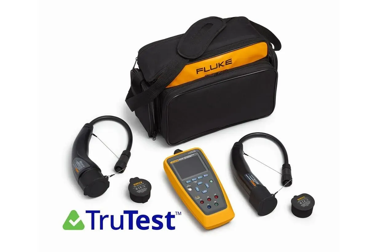
Streamlined Documentation with TruTest™ Integration
Testing is only half the job—documentation proves the work was done correctly. The Fluke FEV350 integrates seamlessly with TruTest™ software to transform raw measurement data into professional compliance reports.
Bi-directional communication means you can create test plans in TruTest™ and push them directly to the FEV350 before arriving on site. Pre-loaded project details eliminate manual data entry and ensure consistent testing across multiple installations.
As tests complete, results sync wirelessly to TruTest™ where control pilot waveform analysis provides clear pass/fail visuals alongside numerical data. Historical site records enable comparison with previous inspections, making it straightforward to identify degradation or changes that warrant investigation.
The result is faster report generation, reduced administrative overhead, and defensible documentation that satisfies building managers, asset owners, and regulatory inspectors alike.
Who Benefits from the FEV350
Electrical Contractors Contractors commissioning new EVSE installations need efficient testing workflows that cover every compliance requirement. The FEV350’s guided sequences and automatic pass/fail determination reduce time on site while ensuring thorough documentation.
Fleet and Facility Managers Organisations operating charging infrastructure for vehicle fleets must verify ongoing safety and performance. Regular testing with the FEV350 catches developing issues before they cause failures or safety incidents, supporting preventive maintenance programs.
EVSE Installation Specialists Dedicated EV infrastructure installers benefit from the FEV350’s comprehensive capabilities and TruTest™ integration. High testing volumes demand tools that maximise productivity without compromising thoroughness.
Certification and Inspection Services Independent inspectors and certifying bodies require instruments that provide traceable, defensible measurement results. The FEV350’s conformance with IEC 61557 performance standards and documented accuracy specifications support professional certification activities.
Built to Fluke Standards
The FEV350 reflects Fluke’s engineering heritage—robust construction, intuitive operation, and measurement performance backed by published specifications rather than marketing claims.
An IP40 protection rating suits typical installation environments, while the temperature range of -10°C to 40°C accommodates outdoor testing across Australian conditions. CAT II 300V safety rating provides appropriate protection for EVSE testing applications.
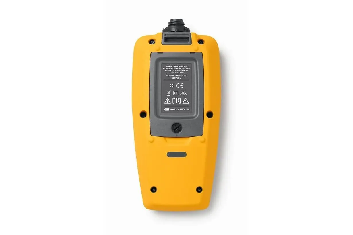
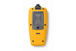
Powering the unit from standard AA batteries—either alkaline or rechargeable NiMH—means you’re never waiting for proprietary battery packs to charge. Swap in fresh cells and continue testing immediately.
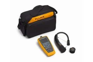
Bluetooth 5.0 connectivity ensures reliable data transfer to mobile devices and compatible Fluke multifunction testers, while the included TPAK magnetic hanger keeps the analyser conveniently positioned during hands-free testing.
TECHNICAL SPECIFICATIONS TABLE
| Specification | Value | What This Means for You |
|---|---|---|
| Input Ratings | 1Φ: 250V max | 3Φ: 230/400V max, 50/60 Hz |
| Connector Compatibility | Type 1 (J1772) and Type 2 (IEC 62196) | Tests all common AC charging connector standards used in Australia |
| RCD Testing | 30mA RCD + 6mA RDC-DD | Verifies both standard residual current and EV-specific DC fault protection |
| RCD Types Supported | Type A, Type B/B+, RDC-PD | Compatible with virtually all EVSE protection schemes |
| CP Signal Analysis | Voltage: ±0.5%, PWM: ±5 digits, Frequency: ±0.001 kHz | Laboratory-grade accuracy for critical communication signal verification |
| State Simulation | CP States A, B, C, D; PP ratings 13A to 63A | Active testing confirms proper charger response to all vehicle states |
| Phase Sequence Detection | L-R-N rotation with imbalance detection | Prevents incorrect three-phase connection issues |
| Voltage Measurement | 0–280V L-N/L-PE, 0–490V L-L | Full range for Australian supply verification |
| Wireless Connectivity | Bluetooth 5.0 (2412–2462 MHz) | Reliable data transfer to TruTest™ software and compatible MFTs |
| Operating Temperature | -10°C to 40°C | Suitable for outdoor Australian job site conditions |
| Dimensions | 263 × 123 × 63 mm (without connector plug) | Compact handheld form factor |
| Weight | ~900g (without plug), ~1.4kg (with plug) | Light enough for comfortable extended use |
| Power | 4 × AA alkaline or NiMH rechargeable | Standard batteries—no proprietary packs required |
| IP Rating | IP40 | Protected against solid objects; use care in wet conditions |
| Safety Rating | CAT II 300V, Protection Class II | Appropriate safety margin for EVSE testing environments |
| Performance Standards | IEC 61557-1, -6, -7, -10 | Documented conformance ensures traceable results |
| Design Standards | IEC/EN 61851-1, IEC/HD 60364-7-722 | Aligned with international EVSE requirements |