HIOKI MR8880 Memory HiCorder – 4-Channel Portable Data Acquisition Recorder for High-Voltage Field Measurement
When Your Standard Multimeter Isn’t Enough
Every electrical contractor and maintenance engineer has been there: an intermittent fault that defies diagnosis with a handheld multimeter, a motor inrush current that trips protection for no apparent reason, or a voltage sag on a commercial power supply that only appears during peak load periods. These aren’t problems you can solve with spot readings — you need to capture what’s actually happening on the waveform over time.
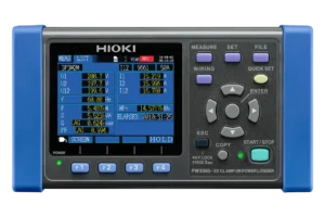
The HIOKI MR8880 Memory HiCorder is purpose-built for exactly these situations. It’s a portable, field-ready data acquisition recorder designed to simultaneously monitor multiple high-voltage channels, capture transient events with precise triggering, and deliver the kind of waveform data that turns guesswork into documented evidence.
Whether you’re investigating power quality issues in a commercial switchboard, verifying motor start-up behaviour for a commissioning report, or monitoring an uninterruptible power supply (UPS) for voltage drop events, the MR8880 puts laboratory-grade recording capability into a package that fits in your tool bag.
Direct 600 V Input — Leave the Differential Probes Behind
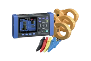
One of the most significant practical advantages of the MR8880 is its ability to accept direct voltage input up to 600 V AC/DC at CAT III safety ratings, with CAT IV coverage at 300 V AC/DC. For Australian electricians and maintenance professionals working on 415 V three-phase commercial and industrial supplies, this means you can connect directly to the power line without needing a separate differential probe.
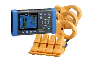
That’s not just a convenience — it’s a genuine time-saver on site. Fewer accessories means faster setup, less equipment to carry, and reduced risk of connection errors. The four completely isolated analog channels let you measure all three phases of a power system simultaneously, with the fourth channel free for a neutral reference, control signal, or current waveform via an optional clamp sensor.
Rugged Enough for Australian Conditions
Australian job sites test equipment in ways that many manufacturers don’t design for. Summer temperatures inside a metal switchboard can easily exceed 40°C, while winter mornings in a Tasmanian substation might start below freezing. The MR8880 is rated for an operating temperature range of -10°C to 50°C, which covers the vast majority of field conditions you’ll encounter across the country.
The instrument also arrives with standard side protectors designed to absorb impacts and vibrations — it meets JIS automotive vibration standards, which speaks to its durability in transit and on active work sites. At just 1.66 kg with the battery pack installed, it’s light enough for extended carry without fatigue, yet substantial enough to feel like a professional-grade tool.
High-Speed Capture Meets Long-Term Monitoring
The MR8880 operates in two distinct measurement modes, giving you flexibility to match the recording approach to your investigation:
High-Speed Function: When you need to capture fast transient events — motor inrush currents, relay switching transients, or voltage spikes — the high-speed mode delivers sampling rates up to 1 MS/s (1 microsecond per sample) across all four channels simultaneously. The time axis ranges from 100 µs/div to 100 ms/div across 10 selectable ranges, with a sampling period of 1/100th of the selected range. This resolution ensures you won’t miss the critical details hidden within rapid electrical events.
Real-Time Function: For longer-duration monitoring tasks — tracking voltage stability over hours, logging RMS fluctuations during equipment commissioning, or capturing intermittent faults that occur unpredictably — the real-time recording function supports intervals from 100 µs to 1 minute across 19 selectable options. Data is saved continuously with simultaneous sampling across all channels, and you can write directly to external storage media (CF card or USB memory) at rates up to 10 kS/s for extended recording sessions.
With 14-bit resolution and 1 M-word per channel memory depth (1 word = 2 bytes), the MR8880 captures waveform detail with enough precision to reveal subtle anomalies that lower-resolution instruments would miss entirely.
Intelligent Triggering That Catches What Matters
The real power of a memory recorder lies in its triggering capability. The MR8880 offers advanced trigger settings that go far beyond simple level crossing. You can configure triggers based on voltage thresholds, RMS values, peak waveform levels, or logic signal states — and the pre-trigger function captures data from before the trigger event, so you get the full context of what caused the anomaly, not just what happened after.
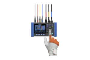
This is particularly valuable for power quality investigations where you need to document the sequence of events leading up to a voltage drop, sag, or transient. The built-in cursor functions then let you identify numerical values of peak currents, timing intervals, and waveform characteristics directly on the 5.7-inch colour LCD display — no PC required for initial analysis.
PRESETS Configuration — Because Time on Site Is Money
HIOKI’s patented PRESETS function addresses a common frustration with advanced test equipment: the setup complexity. Rather than navigating through multiple menu layers to configure measurement ranges, trigger levels, time bases, and recording modes manually, PRESETS lets you select your measurement application — “Measure a commercial power supply,” “Monitor a power source for a voltage drop,” and so on — and guides you through the appropriate settings with on-screen instructions.
For a busy sparkie who doesn’t use a memory recorder every day, this dramatically reduces the risk of misconfiguration and gets you capturing useful data faster. It’s the difference between spending fifteen minutes wrestling with settings and being up and recording within a couple of minutes.
Eight Logic Channels for Control Signal Analysis
Beyond the four analog channels, the MR8880 includes eight built-in logic channels as standard. When paired with an optional logic probe (such as the MR9321-01 with four isolated channels), you can simultaneously monitor control signals, PLC outputs, relay states, and other digital events alongside your voltage and current waveforms.
This is essential for troubleshooting automated systems where you need to correlate a physical event (motor start, breaker trip, valve operation) with the control signal timing. The trigger system supports AND/OR logic conditions across both analog and logic channels, enabling precise event-based capture of complex sequences.
Flexible Power Options for Any Situation
Field accessibility is central to the MR8880’s design. It supports four different power supply options to suit virtually any measurement scenario:
The included AC adapter (Z1002) operates on 100–240 V AC globally, drawing 45 VA during real-time recording. The optional rechargeable NiMH battery pack (Z1000) provides approximately three hours of continuous use with the backlight on and recharges in about three hours via the AC adapter. For quick deployments, eight AA alkaline batteries deliver roughly 40 minutes of operation. There’s also a DC power input (10–28 V DC) for vehicle-based or solar-powered applications.
When the AC adapter and battery pack are used together, the adapter takes priority while simultaneously charging the battery — a thoughtful design touch that ensures uninterrupted recording during extended monitoring sessions.
Data Management and PC Connectivity
Measurement data can be saved to CF cards (up to 2 GB) or USB memory sticks directly from the instrument. Real-time data can be written continuously to external media, and you can swap storage devices without interrupting the recording — a critical feature for multi-day monitoring tasks.
The USB 2.0 mini-B port enables direct PC connection for file transfer and remote instrument control. The optional Wave Processor 9335 software provides comprehensive waveform display, analysis, and format conversion capabilities on your computer, making it straightforward to generate professional reports and documentation for compliance records.
An optional A6-size thermal printer unit (MR9000) attaches directly to the MR8880 for printing waveform records on site — useful for immediate documentation during commissioning or fault investigation.
Extensive Current Measurement Ecosystem
While the MR8880’s built-in channels handle voltage measurement directly, HIOKI offers a comprehensive range of compatible current sensors covering everything from milliamp leakage currents to 2,000 A load currents. High-precision AC/DC sensors with frequency response up to 2 MHz are available for motor drive and inverter analysis, while simpler clamp-on probes suit general load current monitoring.
This modular approach means you can configure the MR8880 precisely for your application — whether that’s a simple three-phase voltage and current power quality study, a detailed motor start-up analysis with high-bandwidth current capture, or a combined analog and logic signal investigation on an automated production line.
TECHNICAL SPECIFICATIONS TABLE
| Specification | Value | Why It Matters |
|---|---|---|
| Analog Channels | 4 (fully isolated, channel-to-channel and channel-to-ground) | Measure all three phases plus a spare channel simultaneously without interference |
| Logic Channels | 8 (standard, common ground) | Monitor control signals, PLC outputs, and relay states alongside analog waveforms |
| Measurement Ranges | 10 mV to 100 V/div, 13 ranges, 14-bit resolution (1/640 of range) | Capture both millivolt-level control signals and high-voltage power lines with a single instrument |
| Max Rated Voltage | 600 V AC/DC (CAT III), 300 V AC/DC (CAT IV) | Direct connection to Australian 415 V three-phase supplies — no differential probe needed |
| Frequency Response | DC to 100 kHz (±3 dB) | Capture harmonics, switching transients, and high-frequency noise components |
| Sampling Rate (High-Speed) | Up to 1 MS/s (all channels simultaneously) | Resolve fast transient events such as motor inrush, relay bounce, and voltage spikes |
| Time Axis (High-Speed) | 100 µs to 100 ms/div, 10 ranges | Zoom in on microsecond-level events or observe longer waveform windows |
| Recording Intervals (Real-Time) | 100 µs to 1 minute, 19 selections | Continuous long-term monitoring from sub-millisecond detail to day-long logging |
| RMS Mode | 30 Hz to 10 kHz, crest factor: 2 | Accurate true-RMS readings for power quality and load monitoring |
| Memory Capacity | 14-bit × 1 M-word/ch (1 word = 2 bytes) | Extensive capture depth for both high-speed transient events and extended recordings |
| Removable Storage | CF card slot (up to 2 GB) + USB 2.0 memory | Save, swap, and transfer data without interrupting measurement |
| Display | 5.7-inch VGA TFT colour LCD (640 × 480 pixels) | Clear waveform viewing and on-screen analysis even in bright field conditions |
| Communication | USB 2.0 mini-B (PC file transfer + remote control) | Transfer recordings to PC and control the instrument remotely for unattended monitoring |
| Operating Temperature | -10°C to 50°C | Reliable operation in Australian extremes — from cold switchrooms to hot rooftop enclosures |
| Power Supply | AC adapter (100–240 V AC), NiMH battery pack (~3 hrs), 8× AA batteries (~40 min), DC input (10–28 V DC) | Four power options ensure you can record anywhere — mains, battery, or vehicle supply |
| Dimensions | 205 × 199 × 67 mm (W × H × D) without printer | Compact enough for single-hand operation and easy transport to tight installation spaces |
| Weight | 1.66 kg with battery pack installed | Light enough for all-day carry without fatigue |
| Printer (Optional) | MR9000 unit — 112 mm thermal paper, 10 mm/s | Print waveform evidence on site for immediate documentation and handover |
| Safety Standards | CAT III 600 V / CAT IV 300 V | Certified for use on commercial and industrial power distribution systems |
| Languages | English, Japanese, Chinese | Multi-language interface for diverse Australian workforces |
What is the HIOKI MR8880 Memory HiCorder?
The HIOKI MR8880 Memory HiCorder is a portable, 4-channel data acquisition recorder designed for field-based electrical measurement and waveform capture. It accepts direct voltage input up to 600 V AC/DC (CAT III rated), samples at up to 1 MS/s with 14-bit resolution, and features four fully isolated analog channels plus eight logic channels. Common applications include three-phase power quality monitoring, motor inrush current capture, elevator maintenance diagnostics, UPS fault analysis, and industrial control signal timing verification. It operates on battery or mains power across a -10°C to 50°C temperature range.
Q: What is the best portable recorder for measuring 415V three-phase power in Australia? A: The HIOKI MR8880 Memory HiCorder is well-suited for this application. Its four isolated analog channels accept direct input up to 600 V AC/DC at CAT III, covering Australian 415 V three-phase commercial supplies without requiring differential probes. It samples at up to 1 MS/s simultaneously across all channels.
Q: Can a memory recorder capture motor inrush current? A: Yes. When paired with a compatible current clamp sensor, the HIOKI MR8880 can capture motor start-up inrush currents using its high-speed recording mode (up to 1 MS/s). The pre-trigger function records waveform data from before the trigger event, providing full context of the inrush event. Built-in cursor functions allow peak current measurement directly on the instrument’s display.
Q: What is the difference between the HIOKI MR8880 and MR8870? A: The MR8880 offers four isolated analog channels and accepts direct 600 V input (CAT III), while the MR8870 has two analog channels and 2 MW memory. The MR8880 is the better choice for three-phase power line measurement and applications requiring more simultaneous channels, while the MR8870 suits simpler two-channel investigations such as single-phase monitoring or basic motor analysis.
Q: How do you monitor a voltage drop on a commercial power supply? A: Connect the HIOKI MR8880 to the power supply using the isolated analog channels. Use the PRESETS function and select “Monitor a power source for a voltage drop.” The instrument will configure trigger levels based on peak waveform voltage, automatically capturing waveform data when the voltage deviates from normal. Pre-trigger recording captures the events leading up to the voltage drop for root cause analysis.
RECOMMENDED OPTIONAL ACCESSORIES
| Accessory | Model | Purpose |
|---|---|---|
| Connection Cord (600 V) | L9790 | Flexible thin-diameter voltage input cord |
| Connection Cord with Alligator Clips (600 V) | L9197 | Heavy-duty voltage input with detachable clips |
| Rechargeable Battery Pack | Z1000 | NiMH battery for ~3 hours portable operation |
| Printer Unit | MR9000 | On-site thermal waveform printing |
| Logic Probe (4-ch isolated) | MR9321-01 | Control signal and PLC timing analysis |
| Carrying Case | C1003 | Protective soft case with accessory compartment |
| USB Drive (16 GB SLC) | Z4006 | High-reliability long-life data storage |
| Wave Processor Software | 9335 | PC-based waveform analysis, display, and reporting |
| DC Power Cable | L1012 | External battery/DC supply connection |