The Risk of Getting It Wrong Is Too High
For any electrical crew working on cable networks — whether you’re cutting into a bundle at a substation, splicing conductors underground, or confirming phasing before energising a new feeder — the consequences of misidentification are serious. At best, you create an unplanned outage and a costly service call. At worst, you put people in immediate danger.
The problem is that modern cable networks are dense. Distribution cabinets are packed with conductors that look identical. Underground routes carry multiple circuits through the same trench. Even experienced technicians can’t rely on colour coding alone when cables age, documentation is outdated, or a bundle has been modified by a previous crew.
What you need is a tool that definitively tells you: this is the cable. Not approximately. Not probably. Definitively.
That’s exactly what the Megger DCI3 is built to do.
One System. Two Critical Functions.
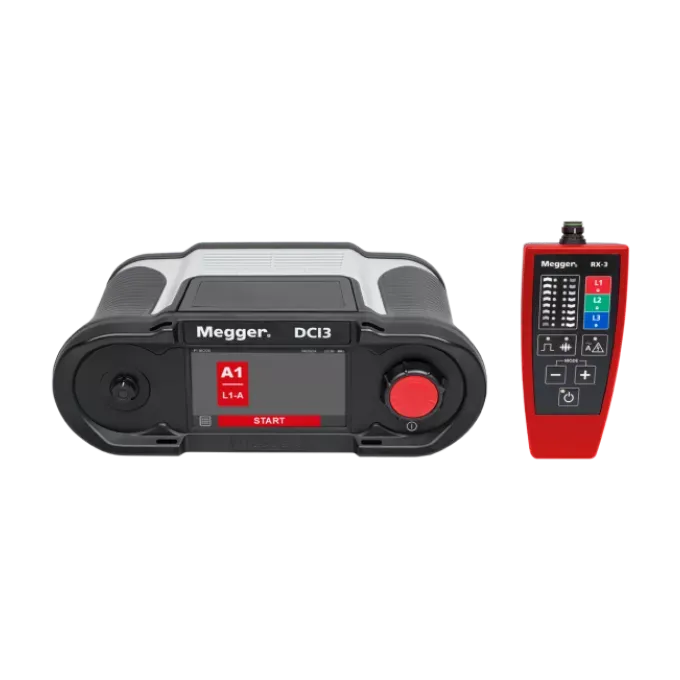
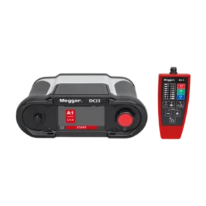
The DCI3 is the first tool many utility crews, cable contractors, and network operators have encountered that combines cable identification and phase identification in a single, field-hardened unit — without requiring the cable to be de-earthed at any point during the process.
Cable Identification (CI Mode)
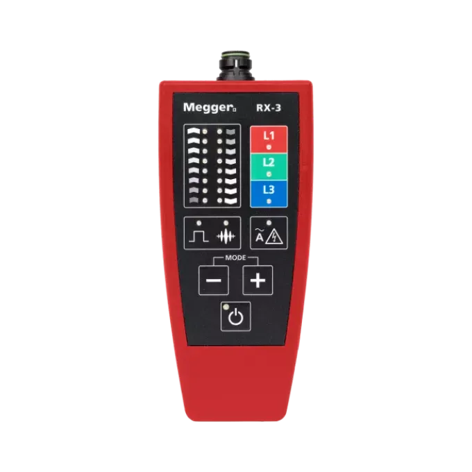
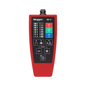
In CI mode, the DCI3 transmitter sends a high-current DC pulse — up to 25 A at 50 V DC — down the cable under test. A technician at the other end uses the RX3 receiver with a flexible inductive clamp to sweep the bundle and identify which cable is carrying the signal. The receiver provides 8 steps of amplification with a 27 dB dynamic range, giving clear discrimination even in tightly bundled installations or when cables run parallel for long distances.
The system works on de-energised low-, medium-, and high-voltage cables up to 30 km in length — covering most distribution network scenarios. For three-phase single-core cable sets, the DCI3 can identify all three phases in a single pass without reconnecting between phases, which is a significant time saving on larger jobs.
Live Cable Identification (LCI Mode — Optional)
With the optional LCI TX-440 transmitter module, the DCI3 extends its capability to energised low-voltage cables operating at 100–440 V AC. This is a genuine safety upgrade for crews working on live LV networks: rather than interrupting supply to identify a cable — which creates customer outages and requires switching authorisations — the transmitter connects phase-to-phase and injects a coded 80 A pulse at 30 pulses per minute. The receiver identifies the correct live cable without any interruption to the circuit.
This isn’t just a convenience feature. For utilities managing supply reliability KPIs or contractors working in occupied commercial buildings, being able to identify cables without de-energising can eliminate hours of coordination and disruption per job.
Phase Identification (PI Mode)
Phase identification is the other half of the puzzle. Before you join cables, connect busbars, or close a new feeder into an existing network, you need to confirm that the phases are correctly sequenced. Getting this wrong can destroy equipment, damage connected loads, or cause serious faults.
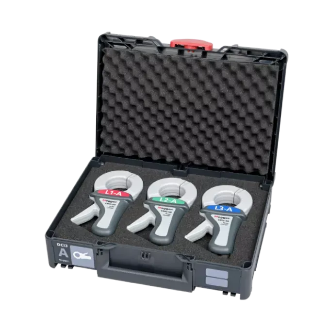
The DCI3’s phase identification mode uses passive CPIC50 clamps that clip over single-core cables while the cable ends remain grounded. The transmitter generates a signal in the 1 kHz–8 kHz band with automatic frequency selection, and the clamps detect which conductor carries which phase. For three-phase sets, all three conductors are identified simultaneously in a single measurement step — no swapping clamps, no reconfiguring.
For larger cable cross-sections or narrow switchgear cabinets where standard passive clamps won’t physically fit, the optional CPIC150-F active flexible clamps (150 mm diameter) handle the job without compromising accuracy.
Built for Real Field Conditions
The DCI3 transmitter is designed around the realities of utility and contractor work:
- IP54 rated (DIN EN 60529): Protected against dust ingress and water splashing from any direction. It will handle a wet trench, a dusty switching station, or a coastal substation without fuss.
- Operating range –10°C to +55°C: Works across Australian conditions from alpine winter sites to industrial environments in Queensland summer.
- Under 2 kg: Compact enough to carry to the worksite without it becoming a burden, yet robust enough to survive the transport case stack.
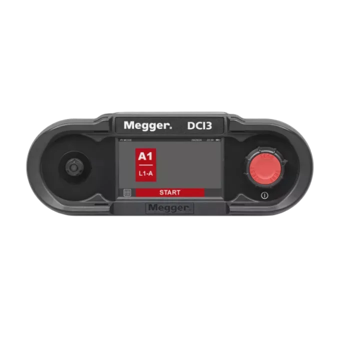
- 4.3″ colour touchscreen (480 × 272 WQVGA): Large, bright display at 425 cd/m² is readable in direct sunlight. The rotary encoder provides an alternative input method if you’re working in gloves.
- Li-Ion battery with 6+ hours CI runtime: A second battery is included in the standard kit, so if a job runs long you’re not hunting for a charger in the field. Fast recharge means the spare is ready for the next shift.
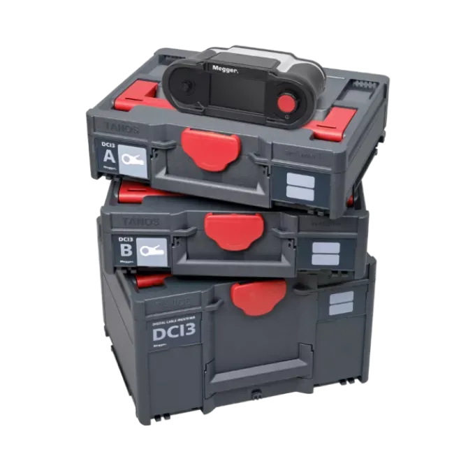
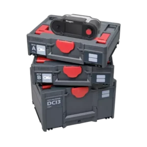
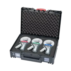
The modular TANOS transport case system keeps everything organised and protected. If your team eventually expands the DCI3 with additional clamp sets or the LCI module, the case stack grows with you — no need to start over with a new carry solution.
Modular by Design — Future-Proof by Default
The DCI3 is available in a range of configurations, and every system option can be retrofitted at any time. If you purchase a CI-only unit today and your scope of work expands to include phase identification or live LV cable work next year, you add the relevant module and a software licence — the base transmitter is already capable.
This modular architecture is particularly practical for Australian utilities and contractors who tender for different types of work across the year. Your capital investment in the DCI3 doesn’t become obsolete as your work scope changes.
Available software licences cover CI-only, PI-only, or combined CI+PI functionality depending on which option modules are fitted.
Applications Across the Australian Network Sector
Electrical Utilities and Distribution Network Service Providers (DNSPs) Identifying cables in crowded substations and distribution boards before planned maintenance or during fault rectification. Confirming phase sequence when energising new feeders or interconnecting substations. LCI mode allows identification on live LV feeders without interrupting supply to customers.
Underground Cable Contractors Locating the correct cable in a multi-circuit trench before cutting or jointing. Avoiding accidental damage to adjacent services during excavation or cable replacement. The 30 km identification range covers virtually all underground distribution runs.
Railway and Transit Electrification Identifying specific cables within complex signalling and traction power cable routes. Confirming correct phasing before connecting new sections of track supply or signalling systems, where a phase error could have serious operational consequences.
Renewable Energy — Solar and Wind Farms Confirming cable identity and phase sequence during AC collection system commissioning or O&M activities. Solar farms and wind projects frequently involve multiple identical cable runs between inverters, combiner boxes, and switchboards — the DCI3 eliminates guesswork at these connection points.
Industrial Facilities and Process Plants Identifying power cables in large motor control centres or distribution boards during planned shutdowns. Phase identification before connecting motor feeders or transformer secondaries to prevent costly equipment damage from phase reversal.
Infrastructure Projects During construction commissioning or handover, confirming cable identity and phasing across long runs between buildings or switchrooms. The DCI3 works at distances where other identification methods become unreliable.
TECHNICAL SPECIFICATIONS
| Specification | Value | Why It Matters |
|---|---|---|
| Cable Identification — CI Mode | ||
| Pulse voltage | 50 V DC | Sufficient signal level for reliable detection over long runs |
| Pulse current (max.) | 25 A | High-current pulse ensures strong signal in large conductors and long cable runs |
| Pulse frequency | 36 pulses/min (CI-1 & DF); 12 per phase/min (CI-3) | CI-3 mode identifies all three phases in one pass — no reconnection required |
| Pulse width | 144 ms | Optimised for receiver discrimination and battery efficiency |
| Maximum operational distance | 30 km | Covers virtually all distribution network cable lengths |
| Phase Identification — PI Mode | ||
| Output bandwidth | 1 kHz – 8 kHz | Avoids interference from power system harmonics |
| Frequency selection | Automatic | No manual tuning required in the field |
| Max. operational distance (with CPIC50 clamps) | 30 km | Same reach as CI mode — consistent across both functions |
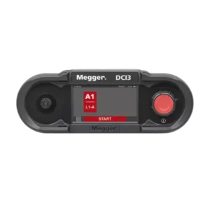
| Transmitter (DCI3 Generator) | ||
| Display | 4.3″ TFT WQVGA, 480 × 272 px, 425 cd/m² LED touch | Bright and readable in direct sunlight; touch + rotary encoder input |
| Measurement category | 300 V CAT IV (DIN EN 61010-1) | Rated for use at the origin of low-voltage installations |
| Protection class | IP54 (DIN EN 60529), Class III (DIN EN 61140) | Suitable for outdoor and switchyard environments |
| Battery | Li-Ion 7.2 V / 4.4 Ah rechargeable (second battery included) | Up to 6 hours CI mode operation; >100 PI measurements per charge |
| Dimensions (L × W × H) | 274 × 96 × 143 mm | Compact enough for single-handed carry |
| Weight | < 2 kg | Field-portable without being a physical burden |
| Operating temperature | –10°C to +55°C | Covers full range of Australian outdoor working conditions |
| Operating altitude | Up to 3,000 m | Suitable for alpine and elevated-site infrastructure |
| Storage conditions | –25°C to +65°C, RH 95% at 40°C | Survives hot vehicle storage between jobs |
| Receiver (RX3) | ||
| Amplification | 8 steps | Fine-tuned sensitivity for dense cable bundles |
| Dynamic range | –3 dB to +24 dB (27 dB total) | Clear signal discrimination even in tightly packed installations |
| Compatible sensors | AZF 250-CI flexible clamp (standard), AZF 150-CI (optional), TFS CI twisted field sensor, PAS CI phase sensor | Multiple sensor options for different cable arrangements |
| Battery | 2 × AA (1.5 V) | > 50 hours battery life; widely available in the field |
| Weight | 0.4 kg | Lightweight for one-hand operation during cable sweeping |
| Protection class | IP54 | Same ingress protection as the transmitter |
| LCI TX-440 (Optional — Live Cable Identification) | ||
| Operating voltage | 100–440 V AC, 50/60 Hz | Covers Australian single-phase (230 V) and three-phase (415 V) LV systems |
| Pulse current | 80 A | Strong coded signal for reliable identification in live LV bundles |
| Pulse frequency | 30 pulses/min | Clear rhythm distinguishable from background electrical noise |
| Weight | 0.5 kg | Adds minimal weight to the field kit |
| Protection class | IP54 | Consistent outdoor protection across the system |
TRADE-SPECIFIC USE CASES
Use Case 1 — DNSP Substation Cable Identification A distribution network crew needs to replace a 33 kV cable termination in a crowded substation where six similar single-core XLPE cables enter the same cable box. After de-energising, the DCI3 CI transmitter is connected at the remote end and the RX3 receiver scans the bundle at the substation end. The correct phase is identified in under two minutes, eliminating the risk of cutting the wrong cable and creating a second fault.
Use Case 2 — Live LV Cable Identification Without Outage A cable contractor is pulling a new circuit through an existing conduit in an occupied office building. Before cutting into a cable tray, they need to confirm which of six grey cables is the one to be disconnected. With the LCI TX-440 module, the transmitter is connected across phases at the board end and the receiver identifies the live cable without switching off any circuits. No tenants are affected.
Use Case 3 — Solar Farm AC Collection System Commissioning During commissioning of a large-scale solar farm near Mildura, the O&M team needs to confirm phase rotation for 24 identical underground AC cables running from string inverters to the main switchboard. The DCI3 PI mode with CPIC50 passive clamps checks all three phases of each cable simultaneously, with results documented for the IEC 62446-1 commissioning report. The job that previously took most of a day is completed in a few hours.
Use Case 4 — Railway Signalling Cable Identification A rail infrastructure contractor is decommissioning a section of signalling cable route and needs to positively identify specific cables among a multi-core bundle before cutting. The DCI3 CI mode with TFS CI twisted field sensor provides definitive identification at up to 30 km — well beyond the cable run length — without any risk of misidentification.
Use Case 5 — Underground Fault Repair in Urban Trench A street-works crew has excavated to repair a damaged cable. The trench contains four circuits in close proximity. Using the DCI3 CI mode, they confirm which cable is the faulted one before making any cuts, protecting the three healthy circuits and avoiding a second outage event that would have extended the incident into a public safety issue.
Use Case 6 — Industrial Motor Control Centre Phasing Before energising a new 415 V MCC feeder in a mining processing plant, the electrical team uses the DCI3 PI mode to confirm phase rotation at the incomer busbar matches the supply transformer. The passive CPIC50 clamps fit over the single-core cable tails while the system remains earthed, completing the check without any need to lift earths or expose live conductors.
Use Case 7 — Network Expansion — New Feeder Connection A DNSP is connecting a new underground feeder to an existing 11 kV ring main. Before the link box is closed, the DCI3 confirms that phase A, B, and C on the new cable align correctly with the existing network. Phase errors at this stage would cause a network fault at energisation — the DCI3 makes this a routine check rather than a risk.
What is a cable identification system used for?
A cable identification system is used to locate and confirm the identity of a specific cable within a bundle or group of cables — typically before cutting, jointing, or maintaining that cable. Field teams connect a transmitter to one end of the target cable and use a receiver with a detection clamp to scan the bundle at the other end, identifying which cable carries the transmitter’s signal. This prevents accidental cutting of the wrong cable, which can cause unplanned outages, equipment damage, or serious personal injury. The Megger DCI3 performs this function on de-energised cables up to 30 km in length across low-, medium-, and high-voltage systems.
What is the difference between cable identification and phase identification?
Cable identification confirms which physical cable in a bundle is the one you intend to work on — identifying it by number or label among multiple similar cables. Phase identification confirms which conductor in a multi-core or three-phase single-core cable set corresponds to Phase A, Phase B, and Phase C — ensuring correct phase rotation before the cable is connected into a network. Both are critical safety steps, but they answer different questions. The Megger DCI3 performs both functions from the same unit.
Can you identify cables without de-energising them?
Yes — with the right equipment. The Megger DCI3 with the optional LCI TX-440 module can identify energised low-voltage cables up to 440 V AC without interrupting the circuit. A transmitter is connected phase-to-phase and injects a coded signal; the receiver identifies the correct live cable at the other end. This is particularly valuable for urban distribution networks, occupied commercial premises, and any application where an outage would have significant operational or commercial consequences.
How is phase identification performed safely on grounded cable systems?
The Megger DCI3 uses passive clamp technology (CPIC50 clamps) that attaches to the outside of single-core cable conductors while the cable ends remain permanently earthed. The transmitter generates a low-level signal in the 1 kHz–8 kHz range and the clamps detect phase-specific signal characteristics without requiring the earth to be lifted at any point. This fundamentally changes the safety profile of the phase identification task — personnel are never exposed to conductors that have had their earth connection removed.
What does IP54 mean on a cable identification system?
IP54 is an ingress protection rating defined by IEC 60529 (DIN EN 60529 in the German standard). The first digit (5) indicates protection against dust ingress sufficient to prevent contact with internal parts, though not full dust exclusion. The second digit (4) indicates protection against water spray from any direction. For a cable identification system, IP54 means the unit can be used safely in outdoor environments, open switchyards, wet weather, and dusty switchroom conditions without risk of internal damage from environmental exposure.


Reviews
There are no reviews yet.