
 Promotions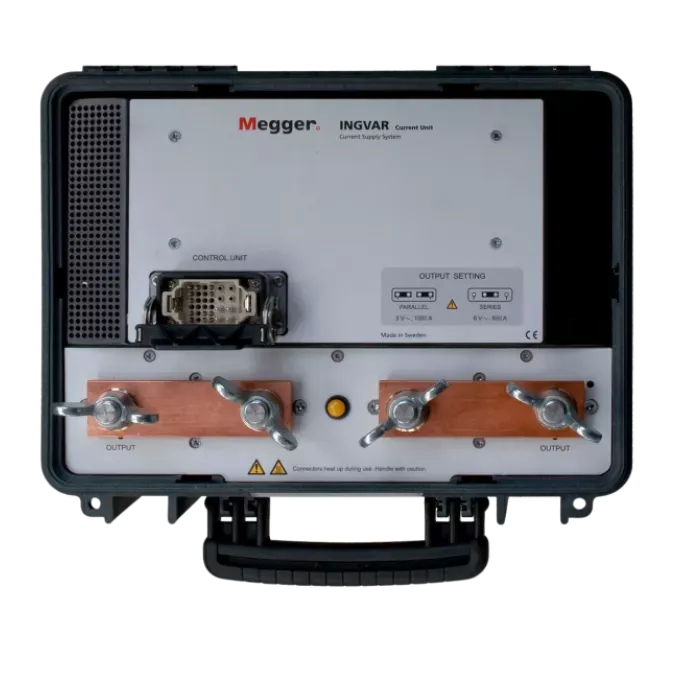


The commissioning problem nobody talks about until the breaker doesn’t trip
You can secondary-inject a protection relay all day and prove the relay logic is sound. What that test doesn’t prove is whether the current transformer feeding it has the ratio stamped on its nameplate, whether the wiring between the CT and the relay is actually continuous, whether the polarity is right, or whether the direct-acting trip unit inside a low voltage air circuit breaker will physically operate when several thousand amps pass through it.
For direct-acting LV circuit breakers, there is no shortcut. The trip mechanism responds to real current through the primary conductors. The only way to verify that an ACB or MCCB trips inside the manufacturer’s published time-current band is to push real current through it and time the result. That’s primary injection, and it’s the reason commissioning engineers, switchboard builders and asset owners across Australia keep a high-current injection set in the fleet.
The practical obstacle has always been the gear itself. Traditional primary injection sets are heavy, awkward single-cabinet units that need a trolley, a tail-lift or three people to move. Getting one into a plant room on level four of a hospital, or into a rural zone substation with limited access, turns a two-hour test into a half-day logistics exercise.
The Megger INGVAR takes a different approach to the same physics.
A high-current test set that splits in two
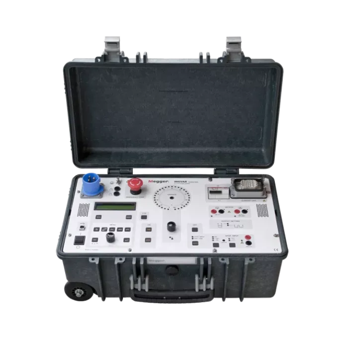
INGVAR is supplied as a system: a control unit and a current unit, connected by a multiconnector interconnection cable. The control unit carries the instrumentation, timing and user interface. The current unit carries the output transformer and current bars. Neither piece is light — the control unit is 20 kg and the current unit is 21 kg — but splitting the mass into two carryable cases changes what’s realistic on site. Two people can move an INGVAR up a stairwell. One person can shuttle it in two trips. That’s a meaningfully different proposition to a single 40 kg-plus cabinet.
Assembly is quick. The current bars on the current unit are configured for parallel or series connection of the outputs depending on whether you need maximum current or maximum compliance voltage, the interconnection cable joins the two halves, and you’re ready to inject.
What “up to 5000 A” actually means in practice
High-current test sets are frequently sold on headline current alone, which is misleading. What matters on a commissioning job is the combination of current, how long you can hold it, and how much voltage the set can push across the loop impedance of your cables and test object.
INGVAR’s published output tables (quoted at 240 V mains input) tell the honest story. With outputs in parallel, the set delivers 700 A continuously at 2.6 V, 1000 A for 30 minutes, 2000 A for three minutes, 3000 A for one minute, and 5000 A for two seconds at 1.2 V load voltage. With outputs in series, you trade current for compliance voltage: 350 A continuously at 5.3 V, 500 A for 20 minutes, and 1500 A for two minutes at 3.5 V.
That series configuration matters more than the headline number for a lot of real work. Higher load voltage is what lets you drive current through a test object with meaningful impedance — a long cable run, a high-impedance safety-ground path, or a CT primary with awkward geometry. Being able to reconfigure rather than being stuck with a fixed output is what makes one instrument cover a broad job list.
Because the top end of the current range demands serious input current from the supply, the achievable output on any given day tracks the quality of your mains connection and the loop you build. The datasheet is explicit about the design criteria: use current cables with a large cross-sectional area, keep the distance to the test object short, avoid open loops that waste energy as magnetic flux, twist the current cables, and make sure every connector is clean and properly tightened. Crews that follow those five rules routinely hit numbers that crews who don’t will never see from the same instrument.
The I/30 function — set up without cooking the test object
This is the feature that experienced primary injection users get excited about, and it deserves plain explanation.
When you’re setting a target current, you normally have to inject at or near that current to find the right dial position. On a CT, a small breaker, or a trip unit you’re about to time, that setup injection heats the sample. Heat changes resistance. Changed resistance changes the result. You’ve corrupted the test before you started it.
INGVAR’s current reduction button scales the output down to one thirtieth. You set up at 1/30 of the target, confirm your dial position, release the reduction, and inject at full current with a cold test object. The same button prevents unintentional tripping during setup — useful when you’re working on a live-adjacent board and don’t want a nuisance operation.
Paired with this is the momentary injection button, which only injects for as long as it’s held, and automatic injection stop, which halts generation after a user-set interval or when the stop-input condition is satisfied.
Timing that doesn’t need extra contacts
For LV breaker trip testing, INGVAR uses internal detection (INT): it records the moment current stops flowing when the main contacts open. No auxiliary contacts to fit, no separate timing leads to run, no arguing about whether the contact block is representative of the main contacts.
If your test needs a different reference, the stop input also accepts an external contact opening or closing, or the application or removal of a voltage, up to 250 V AC / 275 V DC. The timer presents results in seconds, mains frequency cycles, or hours and minutes, spanning 0.000 to 99999.9 seconds and 0 to 9999 cycles, with an inaccuracy of ±(1 digit + 0.01% of value) — plus 1 ms for the stop condition in INT mode.
Output initiation is synchronised to the current zero-crossover point. That’s what gives repeatable results and minimises DC offset, which in turn means the trip time you record on shot three looks like the one you recorded on shot one. Anyone who has tried to defend inconsistent trip times in a commissioning report understands why this matters.
The hold function freezes short-duration readings on the display, and Imax stores the highest current value present for 100 ms or longer — so you capture what actually happened during a two-second injection rather than whatever the display happened to be showing when you looked up.
More than a breaker tester: the measurement section
Where INGVAR separates itself from single-purpose injection sets is the instrumentation in the control unit.
Current transformer ratio testing is displayed directly as the nominal value — 1000/5, for example — with the primary current and either the secondary current or the turns ratio shown simultaneously. No arithmetic, no transcription errors into the test sheet. Secondary circuit burden is measurable and presented in VA.
Polarity testing shows the phase displacement of the currents, with output polarities clearly marked on the unit.
A second measurement channel handles an additional current (Ammeter 2, ranges 0–2 A and 0–20 A) or voltage (0–0.2 V, 0–2 V, 0–20 V, 0–200 V, or auto). From the measured voltage, current and phase angle, INGVAR calculates and displays impedance (Z), active power (P), reactive power (Q), resistance (R), reactance (X), apparent power (S) and power factor (cos φ) — and current and voltage can be presented as a percentage of nominal value, which speeds up any test where you’re working in multiples of rated current.
That calculated impedance capability is what makes INGVAR useful for testing the integrity of safety-ground devices: inject current through the safety-ground and measure the resulting voltage drop to derive impedance.
Where INGVAR earns its keep on Australian sites
Switchboard commissioning and periodic verification. Long time, short time, instantaneous and earth fault tests on air circuit breakers and moulded case breakers, performed phase by phase against the manufacturer’s trip curve. Typical practice is around three times rated current for the long time test, six times for short time, and eight to twelve times for instantaneous — which is exactly the current band INGVAR is built to cover. Note that the ground fault sensor generally needs disabling to test the long, short and instantaneous functions.
Zone substation and industrial CT commissioning. Ratio, polarity and burden verification on new installations, and re-verification after a CT change-out or a wiring modification. The optional CT Switchbox handles up to five secondary windings, short-circuiting the ones you aren’t measuring while you select between them.
Heat runs. Current can be applied continuously or through programmable intervals, with times displayed in minutes and hours for genuinely long-duration testing — useful for busbar, joint and connection work where you’re looking for thermal behaviour rather than trip performance.
Automatic reclosers and sectionalisers. INGVAR can be configured to test breakers with reclosing relays, measuring operating limits, partial times, total times and the number of operations before lockout. User-selectable reclosing sequences can be programmed for sectionaliser testing.
MCCB testing without uninstalling the breaker. The optional HCP2000 High Current Probe lets you test moulded case circuit breakers in situ up to 2000 A trip current — a significant time saving on boards where removing the breaker means an extended outage.
Supply, connection and what to check before you order
INGVAR accepts 100–240 V AC at 50/60 Hz, so Australian 230 V single-phase supply sits comfortably in range. Be aware that the published output tables are quoted at 240 V mains, so real-world output tracks the supply you actually have at the socket. The mains inlet is an IEC 60309 16 A connector, and drawing the highest currents places a substantial demand on the supply — worth confirming your site supply arrangement and lead before the truck leaves the depot.
The instrument’s measurement inputs are rated CAT I with a 2200 V rated transient overvoltage, and the datasheet states it is intended for use in medium voltage substations and industrial environments. Treat the measurement category as a hard constraint in your risk assessment — CAT I inputs are not intended for measurement on mains-supply circuits.
Every INGVAR ships with the interconnection cable, a pair of 120 mm² current cables, mains cable and grounding cable, so the set is ready to inject on arrival. A range of twisted-pair multi-cable high current sets with published impedance figures is available where cable losses are limiting your achievable output.
Megger Sweden AB, the manufacturer, is registered to ISO 9001 and ISO 14001.
TECHNICAL SPECIFICATIONS
| Specification | Value | Why It Matters |
|---|---|---|
| System configuration | Control Unit + Current Unit | Splits weight for site handling and stairwell access |
| Max output current (AC) | 5000 A (parallel, 240 V mains, 2 s max, 1.2 V load) | Covers instantaneous trip testing at 8–12× rated current on most LV breakers |
| Output — parallel, 240 V mains | 0 A continuous (3 V no-load); 700 A continuous (2.6 V); 1000 A / 30 min (2.5 V); 2000 A / 3 min (2.1 V); 3000 A / 1 min (1.8 V); 5000 A / 2 s (1.2 V) | Duty cycle, not just peak current, determines what you can actually complete on site |
| Output — series, 240 V mains | 0 A continuous (6 V no-load); 350 A continuous (5.3 V); 500 A / 20 min (5.1 V); 1500 A / 2 min (3.5 V) | Higher compliance voltage drives current through higher-impedance loops |
| Minimum rest time | 5 min @1000 A; 10 min @2000 A; 12 min @3000 A; 3 min @5000 A (parallel) | Thermal protection reset time — plan test sequencing around it |
| Mains voltage | 100 – 240 V AC, 50/60 Hz | Accepts Australian 230 V / 50 Hz supply |
| Mains inlet | IEC 60309-1, -2, 16 A (3-pin CEE) | Confirm site supply and lead compatibility before mobilising |
| Input current | 20 A @ 240 V for 2 kA out; 45 A @ 240 V for 3.8 kA out | High outputs demand a substantial supply — verify site capacity |
| Measurement category | CAT I, rated transient overvoltage 2200 V | Hard safety constraint — not intended for mains-circuit measurement |
| Ammeter 1 ranges | Serial Low 0–2.15 kA; Serial High 0–3.30 kA; Parallel Low 0–4.00 kA; Parallel High 0–6.50 kA | Range follows output configuration; series connection reduces measurement range |
| Ammeter 1 resolution | 1 A (0–999 A); 10 A (1.00–6.50 kA) | Fine resolution at low currents for CT and trip-unit work |
| Ammeter 2 ranges | 0–2 A / 0–20 A | Reads CT secondary current for ratio and burden testing |
| Ammeter measurement method | AC 50/60 Hz, DC RMS | Handles both AC and DC measurement — select the correct mode or expect ~10% error |
| Ammeter inaccuracy | 1% of range ±1 digit | Defensible numbers for commissioning documentation |
| Voltmeter ranges | 0–0.2 V, 0–2 V, 0–20 V, 0–200 V, AUTO | Millivolt-level resolution for volt-drop and impedance work |
| Voltmeter inaccuracy | 1% of range ±1 digit | |
| Voltmeter input resistance | 240 kΩ (0–200 V range); 24 kΩ (other ranges) | Relevant when loading of the measured circuit is a concern |
| Calculated quantities | Z, P, Q, R, X, S, power factor (cos φ), turns ratio, phase angle | One instrument replaces separate calculation steps on the test sheet |
| Phase angle | 0–359°, resolution 1°, inaccuracy ±2° (readings >10% of range) | Polarity verification and power factor determination |
| Timer presentation | Seconds, mains frequency cycles, or hours and minutes | Hours/minutes display supports long-duration heat runs |
| Timer ranges | 0.000 – 99999.9 s; 0 – 9999 cycles | Covers instantaneous trips through to extended thermal tests |
| Timer inaccuracy | ±(1 digit + 0.01% of value); add 1 ms for INT-mode stop | Trip times you can defend against a published trip curve |
| Stop input max voltage | 250 V AC / 275 V DC | Flexible triggering from external contacts or voltage signals |
| INT level | Threshold approx. 0.5% or 2% of Ammeter 1 range | Adjustable current-interruption detection sensitivity |
| Imax | Stores highest current value present ≥100 ms | Captures peak during short injections you can’t watch in real time |
| Current reduction (I/30) | Reduces output to 1/30 for setup | Set up cold — no sample heating, no nuisance tripping |
| Dielectric withstand | 2.5 kV | |
| Protection | Output transformer thermal cut-out; primary side protected by miniature circuit breaker | Self-protecting under overheating; thermal protection auto-resets on cooling |
| Display | LCD | |
| Languages | English, German, French, Spanish, Swedish | |
| Data transfer | USB Type B female | |
| Operating temperature | 0 °C to +50 °C (+32 °F to +122 °F) | Suits Australian plant rooms and outdoor substation work |
| Storage & transport temperature | −25 °C to +55 °C (−13 °F to +127 °F) | |
| Humidity | 5% – 95% RH, non-condensing | |
| Altitude (operational) | < 2000 m | |
| Pollution degree | 2 | |
| Application field | Medium voltage substations and industrial environments | Manufacturer-stated intended environment |
| Dimensions — Control Unit | 546 × 347 × 247 mm (21.5″ × 13.7″ × 9.7″) | |
| Dimensions — Current Unit | 410 × 340 × 205 mm (16.1″ × 13.4″ × 8″) | |
| Weight — Control Unit | 20 kg (44 lbs) | Two-part design keeps individual lifts manageable |
| Weight — Current Unit | 21 kg (46.3 lbs) | |
| CE marking | EMC 2014/30/EU; LVD 2014/35/EU; RoHS 2011/65/EU | European conformity as stated on the datasheet |
| Manufacturer registration | Megger Sweden AB registered to ISO 9001 and ISO 14001 | |
| Order code | BH-72490 |
Included accessories
| Item | Part No. | Qty |
|---|---|---|
| Interconnection cable, 3 m (10 ft) | GA-12700 | 1 |
| Current cable, 2 m (6.5 ft), 120 mm², 100 mm clamp jaw width | GA-12051 | 2 |
| Mains cable, 2.5 m (8 ft) | 04-00080 | 1 |
| Grounding cable, 5 m (16 ft) | GA-00204 | 1 |
Optional accessories
| Item | Part No. | Notes |
|---|---|---|
| HCP2000 High Current Probe | AA-90165 | Tests MCCBs without removing the breaker; operates up to 2000 A trip current |
| Current Transformer Switchbox | BH-90130 | Handles up to 5 CT secondary windings; shorts unmeasured windings |
| Extension interconnection cable, 5 m (16 ft) | GA-12705 | |
| Extension interconnection cable, 10 m (32 ft) | GA-12710 | |
| Cable set, 2 × 5 m (16 ft), 120 mm², 2.2 mΩ, 15.2 kg | GA-12052 | 100 mm clamp jaw width |
| Multi-cable set 240 mm² (2×120), 2 × 0.5 m | GA-12205 | 0.21 mΩ |
| Multi-cable set 240 mm² (2×120), 2 × 1 m | GA-12210 | 0.32 mΩ |
| Multi-cable set 240 mm² (2×120), 2 × 1.5 m | GA-12215 | 0.42 mΩ |
| Multi-cable set 240 mm² (2×120), 2 × 2 m | GA-12220 | 0.53 mΩ |
| Multi-cable set 360 mm² (3×120), 2 × 0.5 m | GA-12305 | 0.18 mΩ |
| Multi-cable set 360 mm² (3×120), 2 × 1 m | GA-12310 | 0.25 mΩ |
| Multi-cable set 360 mm² (3×120), 2 × 1.5 m | GA-12315 | 0.32 mΩ |
| Multi-cable set 360 mm² (3×120), 2 × 2 m | GA-12320 | 0.39 mΩ |
What is the Megger INGVAR used for?
The Megger INGVAR is a primary current injection test system used to inject up to 5000 A into a test object. Its main applications are trip-time testing of low voltage circuit breakers, current transformer ratio and polarity verification, CT secondary burden measurement in VA, heat runs, automatic recloser and sectionaliser testing, and checking the integrity of safety-ground devices by measuring impedance from injected current and voltage drop.
How much current does the Megger INGVAR produce?
With outputs connected in parallel at 240 V mains, INGVAR produces 5000 A for up to 2 seconds, 3000 A for 1 minute, 2000 A for 3 minutes, 1000 A for 30 minutes, and 700 A continuously. With outputs in series it produces 1500 A for 2 minutes, 500 A for 20 minutes, and 350 A continuously, at higher load voltages up to 5.3 V. Series connection trades maximum current for compliance voltage.
What is the INGVAR I/30 function?
The I/30 function is a current reduction control that scales INGVAR’s output down to one thirtieth during setup. It lets you pre-set the injection current using low current so the test sample doesn’t heat up before the real test, which prevents thermal change in the object from corrupting the result. It also avoids unintentional tripping while the current is being adjusted.
How does the INGVAR measure circuit breaker trip time?
INGVAR’s default method is internal detection (INT), which records the instant current stops flowing when the breaker’s main contacts open — no auxiliary contacts or separate timing leads are required. Alternatively, the stop input can be triggered by an external contact opening or closing, or by voltage being applied or removed, up to 250 V AC / 275 V DC. The timer resolves to 0.000 s with an inaccuracy of ±(1 digit + 0.01% of value), plus 1 ms in INT mode.
Can the INGVAR test medium and high voltage circuit breakers?
No. The INGVAR is designed for primary injection testing of low voltage circuit breakers rated below 1000 V. Medium and high voltage circuit breakers require a dedicated circuit breaker analyser rather than a primary injection set. The measurement inputs on INGVAR are rated CAT I with a 2200 V rated transient overvoltage, and the instrument is intended for use in medium voltage substation and industrial environments — not for measurement on mains-supply circuits.
Does the INGVAR have built-in time-current curves?
No. Current is adjusted manually using the rotary knob, and testing is performed against the breaker manufacturer’s published time-current specifications. Users who need fully automated, curve-driven testing should look at an automated smart primary injection system instead. INGVAR’s strength is manual control combined with a comprehensive measurement section that calculates turns ratio, impedance, power, power factor and phase angle directly.
How do you get maximum output current from a primary injection test set?
Achievable output depends heavily on the total loop impedance you build. Megger specifies five design criteria for INGVAR: use current cables with a large cross-sectional area, minimise the distance to the test object, avoid open loops that increase magnetic flux, twist the current cables together, and ensure all connectors are clean and properly tightened. Supply quality matters too — published output figures are quoted at 240 V mains input.
Will the Megger INGVAR run on Australian mains power?
INGVAR accepts 100–240 V AC at 50/60 Hz, so Australian 230 V / 50 Hz single-phase supply is within its input range. The mains inlet is an IEC 60309 16 A connector. Because published output figures are quoted at 240 V mains, achievable output tracks the actual supply voltage at the socket, and the highest current settings place substantial demand on the supply — site supply arrangements should be confirmed before mobilising.


