
Revolutionize Fault Location, Maximize Solar Production
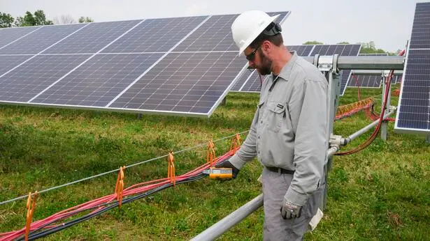
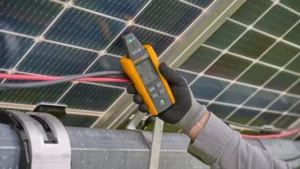
The Fluke GFL-1500 Solar Ground Fault Locator is a frontline troubleshooting tool that helps technicians quickly pinpoint active ground faults in solar photovoltaic (PV) systems.
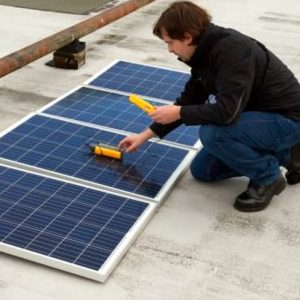
It works by producing a traceable signal in the array, allowing for fast, intuitive, non-contact tracing directly to the fault location. This innovative approach eliminates the frustration of time-consuming, brute-force troubleshooting and reduces unnecessary exposure to electrical hazards.
In addition to improving safety and reducing downtime, this innovative solution redefines how technicians locate active ground faults in solar PV systems. By replacing complex, manual diagnostics with an easy-to-follow trace signal, the GFL- 1500 streamlines fault isolation, helping teams restore system operation quickly and effectively.
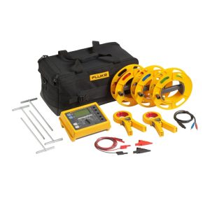
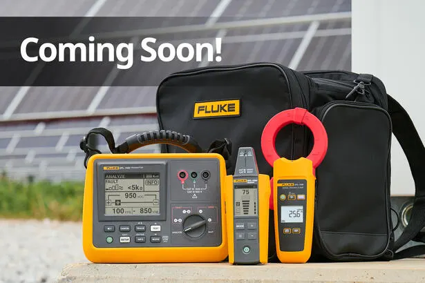
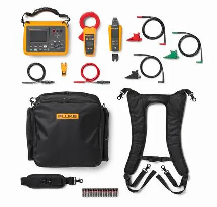
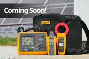
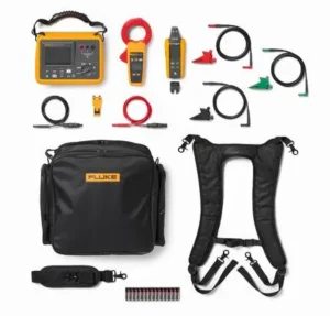
The GFL-1500 Ground Fault Locator is a three-piece troubleshooting system designed to optimize technician workflow in the field, enabling faster and more confident fault resolution. This gives site managers greater assurance in system performance and uptime.
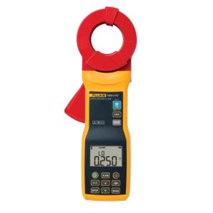
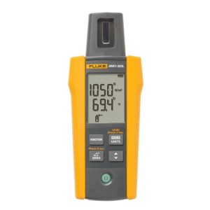
The GFL-1500 system consists of the GFL-1500 Transmitter, GFL-1500 Receiver, and GFL-1500 Signal Tracing Clamp.
FaultTrack™ Technology — Solar Ground Fault Detection
The GFL-1500 utilizes FaultTrack™ Technology to detect active faults and generate a traceable signal through the fault path. This enables technicians to follow that signal from the transmitter through the faulted path to the precise point of failure. Pinpointing the exact location of an active fault used to be a challenge—with FaultTrack™ Technology, that work is easier than ever.
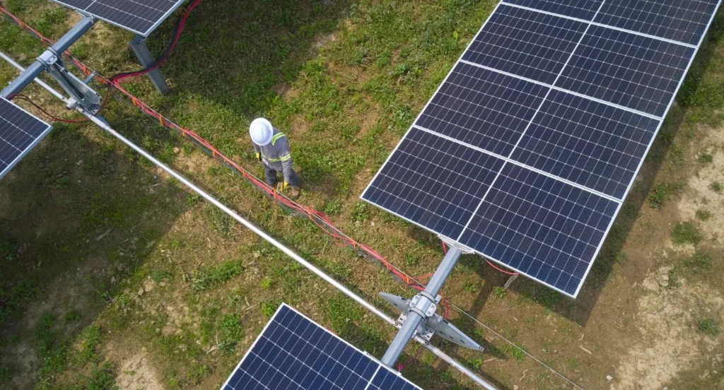
In large-scale solar arrays, the challenge of finding active faults is often exacerbated by the difficulty of identifying string layouts with incomplete or outdated documentation. With a general understanding of your site’s configuration, just a few connections, and non-contact tracing, the GFL-1500 enables technicians to identify the faulted branch and pinpoint the fault location within a string—without relying on detailed site maps or time-consuming test procedures.
By combining multiple diagnostic functions into a single, easy-to-use system, the GFL-1500 delivers an unmatched ability to locate faults with non-contact signal tracing, making it an essential tool for high-efficiency solar maintenance and troubleshooting.
FaultTrack™ Technology — Solar Ground Fault Detection
The GFL-1500 utilizes FaultTrack™ Technology to detect active faults and generate a traceable signal through the fault path, enabling technicians to follow that signal from the transmitter through the faulted path to the precise point of failure. Pinpointing the exact location of an active fault used to be a challenge—with FaultTrack™ Technology, that work is easier than ever.
In large-scale solar arrays, the challenge of finding active faults is often exacerbated by the difficulty of identifying string layouts with incomplete or outdated documentation. With a general understanding of your site’s configuration, just a few connections, and non-contact tracing, the GFL-1500 enables technicians to identify the faulted branch and pinpoint the fault location within a string—without relying on detailed site maps or time-consuming test procedures.
By combining multiple diagnostic functions into a single, easy-to-use system, the GFL-1500 delivers an unmatched ability to locate faults with non-contact signal tracing, making it an essential tool for high-efficiency solar maintenance and troubleshooting.

Ease-of-Use and Time Savings
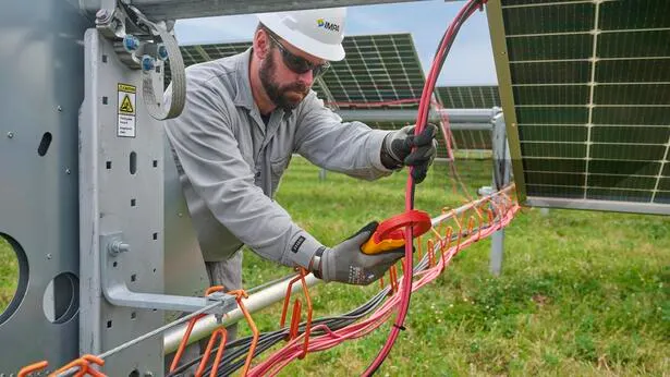
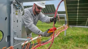
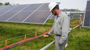
The GFL-1500 is built to simplify solar ground fault detection in the field. From a central test location, technicians can begin tracing the fault path without repeatedly disconnecting conductors and brute-force testing each individual string.
This streamlined approach saves valuable time and increases troubleshooting safety, enabling your team to solve problems quickly and confidently.
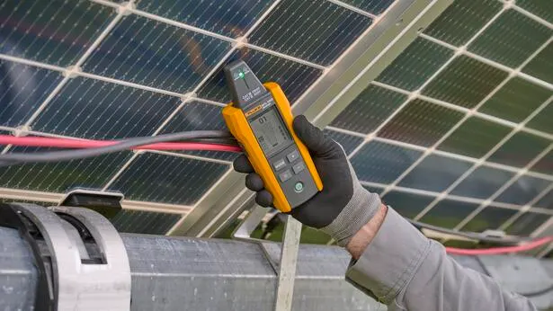
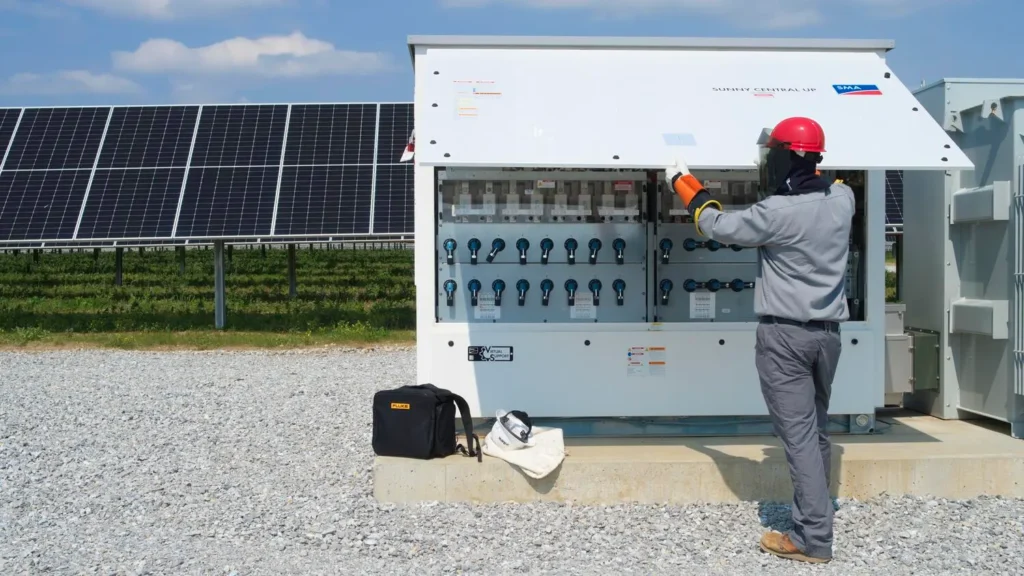
The GFL-1500 system includes both a signal tracing receiver and clamp, each suited to different stages of the diagnostic process. The clamp is especially useful for identifying the faulted combiner or string without making disconnections, even in noisy environments where signal clarity may be reduced.
Once the affected solar string is identified, the signal tracing receiver or clamp can be used to precisely follow the fault path and pinpoint the issue within the string.
Designed for real-world conditions, the GFL-1500 is intuitive to operate, quick to deploy, and built for harsh environments, delivering an end-to-end troubleshooting solution that enables technicians to move efficiently from problem to resolution.